Saturday, February 15, 2020

Page 32-11: Installing and tensioning cables

I built the wooden structure for positioning the rudder pedals for cable installation out of scrap wood, then hooked up the rudder cables.  The cables are pulled through the tail cone using strings taped in there much earlier in the build.  This pulls them through all the bushings, ready to attach to the
stabilator.  Easy, if I hadn't managed to let one of them fall back into the tail cone (twice).  I had to make a long, skinny, flexible piece of wood, push it through the tail cone and all the bushings, then re-pull the string.


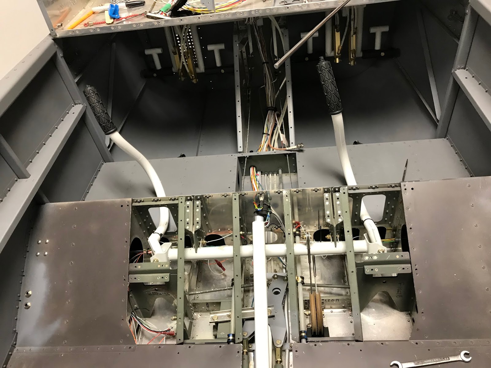
In the pic below you can see the forward attach point for the rudder cables, and the cables passing through the bushings in the forward-most bulkhead.  These cables have zero tension until feet press
the rudder pedals.  The control sticks appear to not be parallel due to the short focal length of the lens in my iPhone.  They're parallel to within a degree or so.  I tried to convince myself that the sticks should be canted inward a bit, making a more natural-feeling wrist angle, but didn't like to look.

The seat ramp cover is removed in this pic, but had to be re-installed before tensioning the stabilator cables to prevent a slight distortion of the structure due to the tension.


The pic at right shows the cables attached to the rudder.  Here's where I accidentally let the cables slip back through the holes while I was trying to get the correct washers in and lined up before bolt insertion.

Steel straps are fabricated to set the correct length of the cables when they're attached to the rudder.  These attach at the front end of the cables.


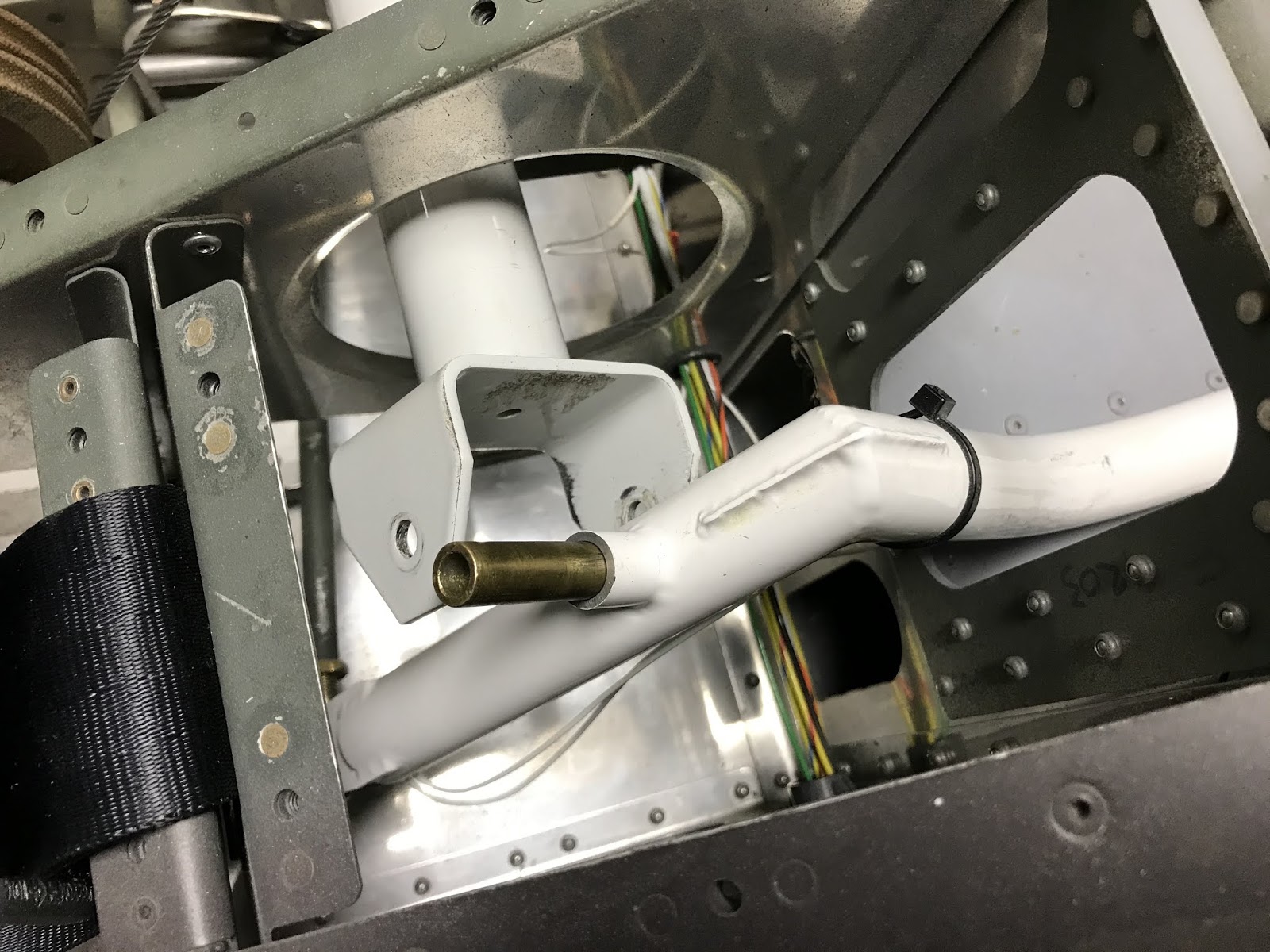
To set the tension for the stabilator cables, the control stick is positioned as shown using a fabricated 41-inch stick going from the back of the control stick to the longeron.  The front of the control stick
must be 10 inches from the panel.  The build manual is a bit vague here.  I assumed that, with the control stick in this position, both stabilator cables should be set to 35 lbf - 45 lbf as prescribed in the build manual and proceeded to do this.  I had erroneously assumed that this control stick position would cause the moments on the pulleys to cause the tensions in each cable to be equal.  Not so.


The tension is set using turnbuckles.  The cables themselves are prevented from rotating using the coat-hanger tool shown, while the turnbuckle is rotated, tensioning the cable.  This is done through the inspection holes in the bottom of the fuselage while lying on your back.  It's all trial-and-error:
Rotate the turnbuckle, crawl out from under the fuselage (a mechanic's creeper helps here), measure the tension, repeat.  Measuring the tension requires a tensionometer, which the build manual suggests can be borrowed.  The people who typically own these are A&P mechanics, who opined on Vansairforce.com that they would never lend these expensive tools out.  Can't blame them.  Since I'll have to check the tension yearly during the condition inspection, I bought one.


The repeatability of this instrument worried me a bit, but I finally set both cables to about (as close as I could read) 41 lbf.  The stabilator movement feels good and, after farting around with it for days, I declared it done.
After the cables are judged to be at the correct tension, the blue clips are installed (shown in the final pic).  The kit comes with four of these, so if you have to re-set tension after installing the clips, you're SOL.  They cost 8 cents each, so I ordered ten or so.  Right away, I needed them.

I don't feel great about this tensioning process.  They're set at 41 lbf, but if I pluck the stabilator cables, they rattle a bit in the bulkhead holes.  Several of these holes are not fitted with a grommet, and I'm guessing the cables shouldn't hit.  I may enlarge the holes a bit with a drum sander on a Dremel tool.  Normal operation of the stick seems fine.  My worry at this point is that installing the autopilot servos will affect the effort required to move the sticks.  I'll find out soon.

The blue clips are clearly shown in the final pic and require that a slot in the cable end line up with an internal slot in the barrel.  This whole tension process seemed a bit imprecise.

Monday, February 10, 2020

Page 32-05 Revisited: Control Stick Bushings


After installing the stabilator cables (post to follow) I spent some time moving the stick around and watching the stab move.  I could definitely feel play in the stick.  If I held one stick full forward, I could move the other stick about 1/16th inch at the top.  After trying to convince myself that "It
doesn't matter, I'll never even notice it while flying," I decided I couldn't accept it.  In my head I'm hearing the experienced builders whispering to me.  They're saying "Perfection is the enemy of flying your airplane."  I ignored the whispers.

In the picture at left, I have unbolted the stick and pushed out the bushing.  The bushing gets clamped tightly between the ears on the cross shaft, and relative motion occurs between the ID of the steel tube passing through the stick and the OD of the bushing.  For fore-and-aft motion of the stick (controlling pitch) I could feel the play, for lateral motion (roll) I could feel no play.  The problem arose when I originally reamed the ID of the steel tube.  The OD of the bushing from the factory was 0.375 inches (plus a bit) and wouldn't come close to passing through ID of the tube.  I lightly reamed the ID (using the red neck reamer shown -- a bolt with the head cut off and an axial slot which anchored a strip of #200 sandpaper).  I was able to borrow an actual 0.375 reamer and it passed easily through the tube.  Slightly
larger reamers were apparently, based on their prices, diamond coated and I couldn't afford to buy one for two passes through the tube followed by retirement to the reamer drawer in my toolbox.  The odd thing was that the bushing would pass 80% of the way through the tube starting from either end.  I decided the only way this could happen was if the ID of the steel tube was correct but the tube was very slightly bent in an axial direction.  Here's where I made the mistake: I reamed it a bit more until the bushing would go all the way through, then assembled everything.  This got me the end-to-end play when moving the stick fore and aft.

After determining that I couldn't stand the play, I had slightly oversized bushings made (thanks Joe), then carefully sanded the OD of the bushing into a slight hour glass shape (OD smaller in the middle).  Pilot's side is perfect, co-pilot's side still has slight play (I'll never fly from that side!).  The red neck lathe is shown (bushing held on a bolt which was chucked into my drill).