Friday, December 25, 2020

Let there be light (and heat)

A southern boy tries to survive his first full winter in Colorado 

Although we've had this house in Colorado for about five years, we've mostly spent summers here with a bit of fall and spring thrown in.  This first full winter as a hangar owner quickly showed me that working on a metal airplane in really cold weather is difficult.  I used my "salamander" heater more than I should have (it says right there on the heater "Do not use in enclosed spaces") figuring that the hangar was leaky enough that I was safe breathing the products of combustion if they were somewhat diluted.  I finally bit

the bullet and had sprayed-in foam applied to the ceiling and door, and since I was already hemorrhaging money I bought and installed a Mr. Heater 80,000 BTU/hr gas heater.  To be truthful, my hangar neighbors (thanks Chad and Tom) did essentially all the work running the gas line, installing the meter and heater, running the wiring and since the were already up there, installing three more super-bright LED ceiling lights for a total of four (brand name is UFO Deformable, 7200 lumens, 6000K color temperature, $24 each on Amazon).  I believe they were concerned that a person my age shouldn't be 18 feet in the air doing that stuff -- looks like my feeble old man act worked.  I did run the conduit and wire around the walls to install 20 new electrical outlets, allowing me to make the fire inspector happier by getting rid of all the extension cords.

The picture shows the heater mounted at the ceiling, and you can also see the blown-in foam (R-28) which looks like Mammatus Clouds (my favorite kind).  The insulation on the bi-fold door looks the same but in a vertical plane.  All that's lacking is the centrally located ceiling fan, which I bought and assembled today.  This should cure the current situation where all the hot air stays at the ceiling while the air below stays about 55 F.  Even with the stratification, it's a huge improvement.  Next comes the fiberglass part of the canopy.  All the endless trimming and trial fitting of the canopy is finished (blog post to follow).

Since we're talking about the future, the engine kit has arrived!  Here's what $30,000 will get you these days:

Engine, prop, ducts, hoses, wires, everything forward of the firewall, causing my wallet to be much lighter.  The good news is that this is the next-to-last kit.  I'll order the avionics kit as soon as I settle on which bank to rob.  Using dollars per cubic meter as a metric, that box will win by a long shot.

Thursday, September 10, 2020

Page 25A: Installing the Plexiglas rear window -- an expensive tale of woe

 Note: This work occurred back in North Carolina, before the big move to Colorado, so we're a bit out of chronological order.

The kit as I ordered it came with a Lexan rear window (still in its protective plastic back in NC -- one of many parts paid for but not used) which was subject to crazing when exposed to even the smallest amount of gasoline.  The location of the fuel filler made it almost impossible to avoid this fate, so the Mothership came out with a replacement made of plexiglass (Plexiglas) which solved the problem.  Naturally, I ordered this, never missing an opportunity to spend even more money.


The first step in the installation called for carefully positioning the window fore and aft as well as side to side before drilling the first hole, after which further position adjustments were impossible.  I spent countless hours on this step, which makes what happened hurt even worse.  After clamping the window to the roll bar, I drilled that hole.  You can see the cleco center aft in the first two pictures.  Getting the window into this position required lots of fiddling.

The window fits over the roll bar at the forward edge but under the tail cone skin at the aft edge, meaning there's nothing to hold the Plexiglas against the inside of the aluminum skin.  To solve this problem I fabricated two flexible braces from PVC (shown in the pic).  With the plexi held firm, I felt confident in the final measurements, ensuring a good fit.  

Having to repeatedly clamp and unclamp the forward edge while repositioning the aft edge and taking measurements all around proved to be challenging.  I wasted a lot of time here.

To safely drill or cut plexi without fear of cracking, the temperature should be above 70 F, easy to do in NC in the spring.


In order to match drill the holes in the unsupported plexi along the aft and bottom edges, a helper was needed to hold a block of wood firmly against the inside of the plexi while the hole was drilled from the outside.  The Spousal Unit (a.k.a. Dr. KTH) was pressed into service for this task.  Her ghostly image can be seen through the protective plastic sheet covering covering the window.

The sequence for this drilling is specified in the build manual. Certain #30 holes are matched drilled through the aluminum skin alternating with certain #40 holes through the window and roll bar.  Clecos are inserted after drilling each hole.  Everything looked good.  Little did I know.

Then came the bad part.  Each #40 hole through the plexi and roll bar (thick aluminum) is to be enlarged to #36 with a reamer then tapped 6-32 and the appropriate screw inserted.  All holes, including the tapped ones, are to be enlarged to #27 later.  This is very unclear in the instructions and many builders didn't enlarge the tapped holes.  I started on the lower right side tapping the holes and had made it though about 75% of them when the tap shattered, cracking the window ($500).  I was using best practices, backing the tap out to clear chips every turn.  From the start it seemed that the tap was requiring an uncomfortable amount of torque going through the aluminum and plexi at the same time. If I had it to do over, I'd go straight to the #36 bit, skipping the #40, and I wouldn't tap the plexi.  All drilling of the plexi was done with bits made for this purpose and all enlarging of holes was done with a reamer or a UniBit (step drill).

After removing the window, I tapped the remaining #36 holes in the roll bar (very low torque required) and ordered a new window.  I was now faced with figuring out how to drill the roll-bar holes in the new window and make make them line up with the already-drilled-and-tapped holes.

Now extremely gun shy about working with Plexiglas, I repeated the whole process (complete with Spousal Unit inside), but eyeballed where to drill the #40 holes so that they were concentric with the existing tapped holes, not wanting to damage the existing threads.  My thinking was that enlarging the holes in the plexi later to #27 (as called for) or 5/32 (if needed) would handle any eccentricity.

The pic shows the #30 holes clecoed and the screws placed in the roll bar.  The tape around the lower and rear borders is positioned 1/32 inch (eyeballed!) from the aluminum to limit where the ProSeal goes in the final installation.  I'll wait until much later in the build to permanently attach it.  The tape on the forward edge of the canopy marks the line to which the plexi is to be trimmed, lining the leading edge up with aft edge of the forward half of the roll bar.  The trimming was done with a cabinet makers scraper.  Plexi responds well to scraping but poorly to cutting, explaining why a reamer or UniBit is ideal.  I wish UniBits came in number sizes.


Saturday, June 20, 2020

Moving the project to Colorado

When I started this build 9 years ago, with my usual hubris it never crossed my mind that I wouldn't finish the airplane in North Carolina and fly it to Colorado where it would be based for the duration.  Years dragged by with progress which could sometimes be characterized as glacial, so I found myself retired (after teaching Mechanical Engineering at UNC Charlotte for 34 years) with the spousal unit accepting a faculty position in the Mechanical Engineering department at Colorado State University.
 After much soul searching I decided to do what I recently swore I'd never do: move the project by truck across the country.  Reading other peoples' blogs, it seemed that most people did it themselves.  My best estimate on the cost of renting a 22-foot truck and paying for the Diesel fuel was $1600 (probably low).  I discovered Stewart Transport, who specializes in moving light aircraft, and found their quote to be $2500.  This $900 delta turned out to be some of the best money I've spent.  Shelly and Mark showed up in the most impressive 18-wheeler I've ever seen, outfitted with a special crane for loading the fuselage, with the wings being strapped to the walls in padded slings.  This was much better than I had envisioned doing it myself and it was definitely a good thing it was done so well: winds through Kansas and Colorado were consistently gusting to 40 mph (direct cross wind), forcing many 18-wheelers to park for a while.  I don't want to even think about me in a lightly-loaded truck having to deal with that.

The Mothership recommended that I build a false spar made of 1-inch plywood with holes for the spar pins and holes for tie down purposes (these weren't used).  The crane attached to this and the nose wheel strut.  Worked perfectly.

After loading, my two dogs and I raced the truck to Colorado -- barely beating them -- where we unloaded at my new hangar.  Feels great to utter those words: my new hangar.  I had been on a wait list for a hangar both in North Carolina and Colorado for many years, making no apparent progress toward a rental unit.  After checking prices on purchasing a hangar I put that out of my mind.  Then, out of the blue, I got a personal message on Vansairforce.com (thanks, Ken) about the availability of a T-hangar at KLMO (1.5 miles from my house) for $40k, almost too good to be true (it even has an electrically operated door!).  Of course, that's part of the money I needed to buy the firewall-forward kit and the avionics kit, but that's another story.  KLMO is a hotbed of experimental aircraft activity, with lots of RVs including two other RV-12s.

In a previous post I bragged that I'd built the fiberglass tailcone fairings without removing the stabilator.  I went on to say that I'd fly the airplane having installed the stabilator (an odious task) only once.  So much for that.  It had to come off to fit in the truck.  I constructed a stand just the proper height to support the stabilator while removing the two 1/4-inch bolts (kinda scary) which hold it on the airplane.  The bolts can then be accessed with an 8-inch extension connected to the 7/16th socket with a universal joint, allowing for the required misalignment.  A big contributor to making the process a PITA is the lead counterweight which sticks a couple of feet into the tailcone.  The shaft holding it, the aft end of which is seen in the picture, must be unbolted and rotated 90 degrees to fit through the hole in the aft-most bulkhead in order to be withdrawn, an awkward process for one person.  The most maddening thing, however, is having to remove the tension from the stabilator cables (see previous post) only to redo it upon arrival in Colorado.  Here it is in its new home.
                                                     
The sequence of events which lead to this massive relocation from my ancestral home in the South to my new home in Colorado almost seems preordained.  Every piece of the puzzle fell into place without any effort.  If I were religious or otherwise mystical I'd attribute it to some power beyond my understanding.  Alas, I must attribute it to happenstance: the spousal unit (my beautiful and talented wife, Karen) became interested in triathlon, attended Dave Scott's triathlon camp in Boulder, spent the following summer training with him and completing the Boulder IronMan two summers in a row, by chance trained with the number one real estate guy in Boulder (thanks Sasha) who put us onto an amazing house in Longmont, was able to teach summers at CU Boulder, then got a faculty position at CSU.  Every piece of the puzzle fell neatly into place.  I'm still amazed by it all.


Monday, March 2, 2020

Page 44: Autopilot servos

Considering that I want to get everything that goes beneath the seats and baggage compartment panels installed in preparation for closing all that up, the time had come to make a fairly big decision: Garmin or Dynon autopilot?  I had intuitively been leaning toward Dynon rather than the 800-pound
gorilla.  Not sure why.  I knew that Dynon map updates were free for life, but a visit to Mothership's website which shows the cost of all the bits and pieces I'm going to have to buy sealed the deal.  For the single display (can't afford dual), autopilot servos, knobs panel (optional but makes setting the autopilot easier in flight), ADSB in and ADSB out, the Dynon was about $2500 cheaper.  With all the other stuff in the avionics kit (radio, intercom, etc.) the total cost for the Dynon is $18,995.  A staggering amount of money for a guy about to retire, but I have no choice.


The title of the picture above is "Two Autopilot Servos and a Meat Servo."  Each AP servo -- one in each hand -- costs over $800.  The meat servo between them is the chump footing the bill.  You can see that I've installed the canopy frame.  The rear window is hugging the tail cone, waiting for a trial fit.


One of the first steps involves stripping all the wires from the two servos, 14 wires in all, and crimping a .093 Molex pin on each.  A good crimp tool is a must for this, but even with the best available from Klein Tools I managed to screw up a few and had to re-order.  The stripper from Klein (shown) is also well worth the money.


There's definitely a technique involved in making the crimps.  There are two sets of tabs involved,
with the outer set making a bear hug on the insulator and the inner set plunging into the conductor.  After each crimp, I gave the Molex pin a fairly hard pull.  A few failed the test and had to be re-done.  The picture shows an average crimp.

When each seven-wire set is crimped, the pins have to be inserted into a 9-position Molex connector which will plug into an opposite gender plug installed much earlier in the build during the wiring harness installation.  Each pin must go into the correct hole in the connector, of course, and there's a very clear diagram to help facilitate this.  After doing it correctly, I gave one last tug and one of the wires came out!  This required removing an already-inserted Molex pin from the connector, which is an odious task.  Quite a few swear words followed this event.


Installation of the servo motors was fairly straight forward.  I was immediately able to allay my previously mentioned fears about the effort required to operate the control stick with all the AP hardware installed.  You can feel some added resistance to movement, but not much.


Pic above shows roll servo, pic below shows pitch servo.

Saturday, February 15, 2020

Page 32-11: Installing and tensioning cables

I built the wooden structure for positioning the rudder pedals for cable installation out of scrap wood, then hooked up the rudder cables.  The cables are pulled through the tail cone using strings taped in there much earlier in the build.  This pulls them through all the bushings, ready to attach to the
stabilator.  Easy, if I hadn't managed to let one of them fall back into the tail cone (twice).  I had to make a long, skinny, flexible piece of wood, push it through the tail cone and all the bushings, then re-pull the string.


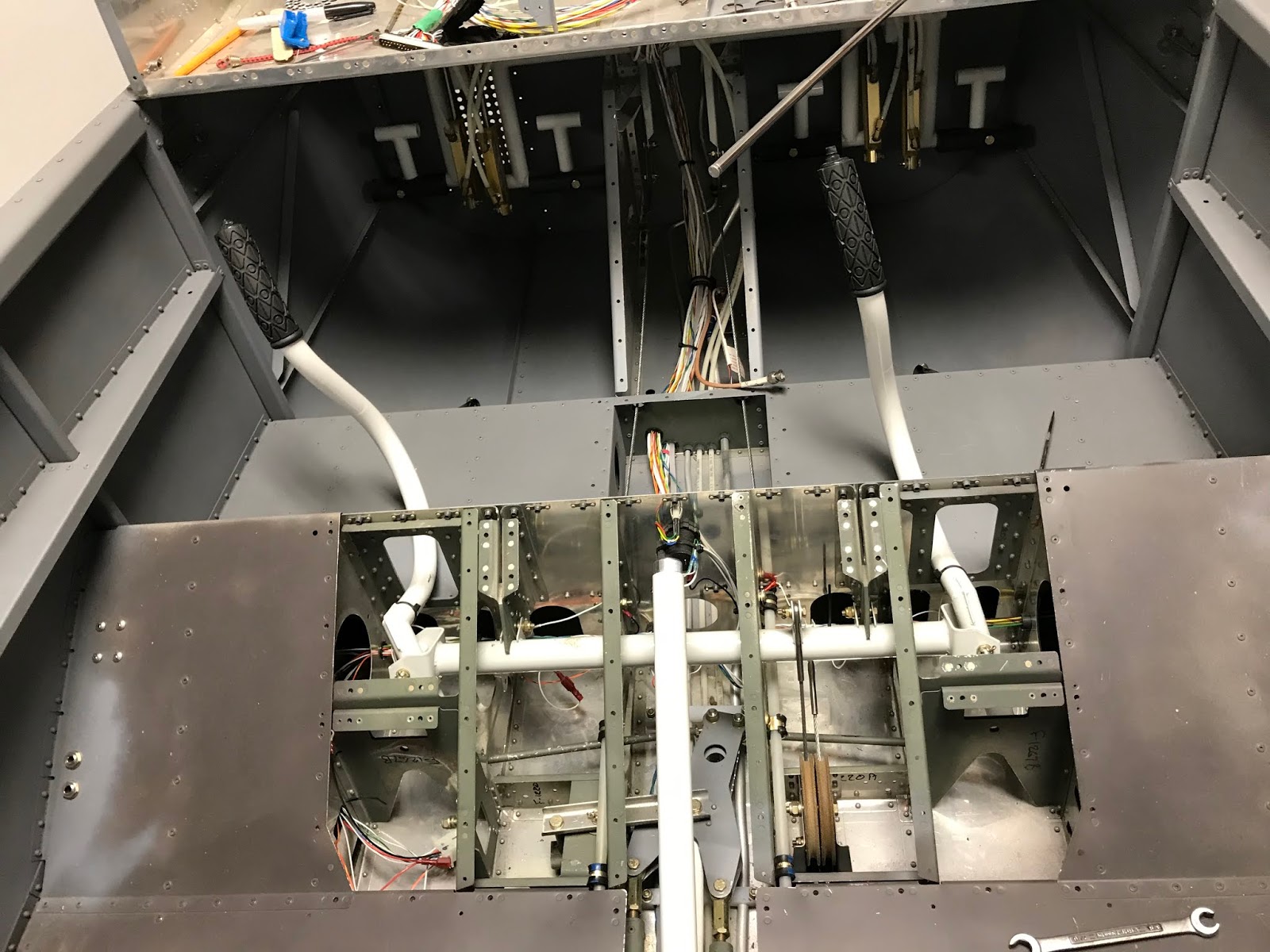
In the pic below you can see the forward attach point for the rudder cables, and the cables passing through the bushings in the forward-most bulkhead.  These cables have zero tension until feet press
the rudder pedals.  The control sticks appear to not be parallel due to the short focal length of the lens in my iPhone.  They're parallel to within a degree or so.  I tried to convince myself that the sticks should be canted inward a bit, making a more natural-feeling wrist angle, but didn't like to look.

The seat ramp cover is removed in this pic, but had to be re-installed before tensioning the stabilator cables to prevent a slight distortion of the structure due to the tension.


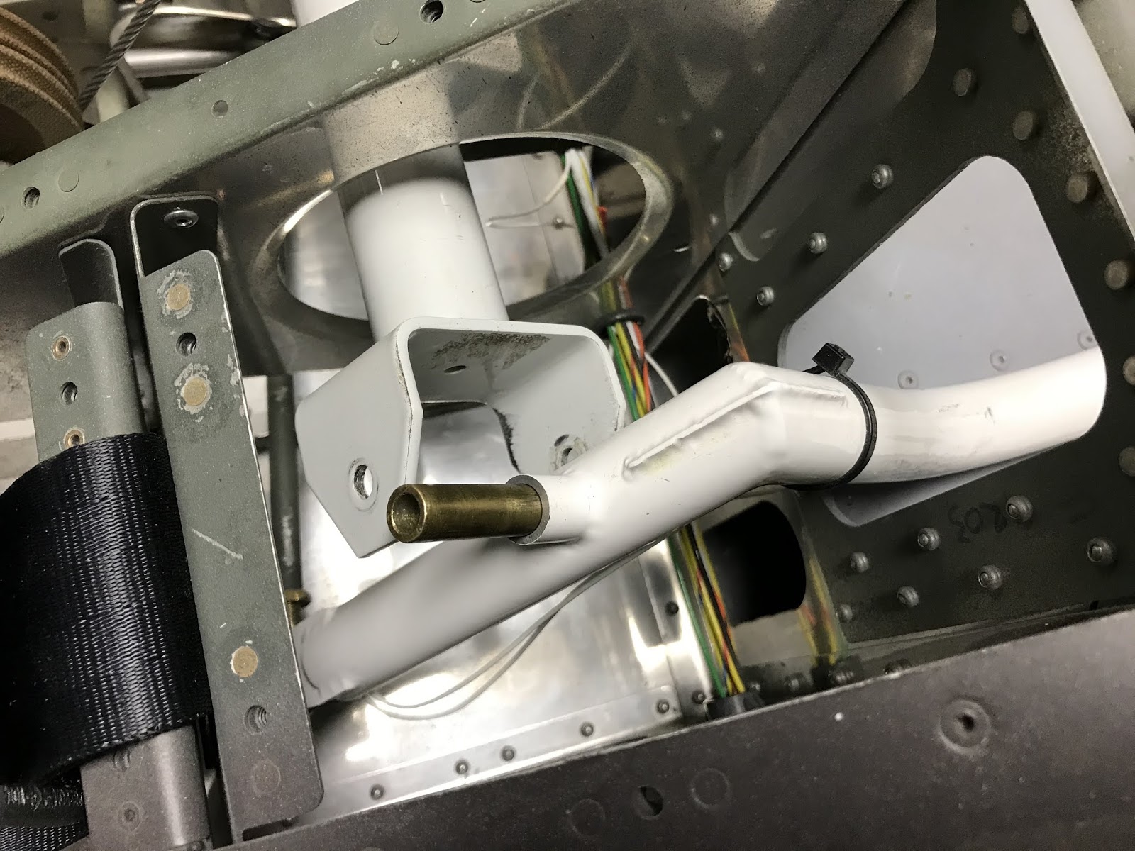
The pic at right shows the cables attached to the rudder.  Here's where I accidentally let the cables slip back through the holes while I was trying to get the correct washers in and lined up before bolt insertion.

Steel straps are fabricated to set the correct length of the cables when they're attached to the rudder.  These attach at the front end of the cables.


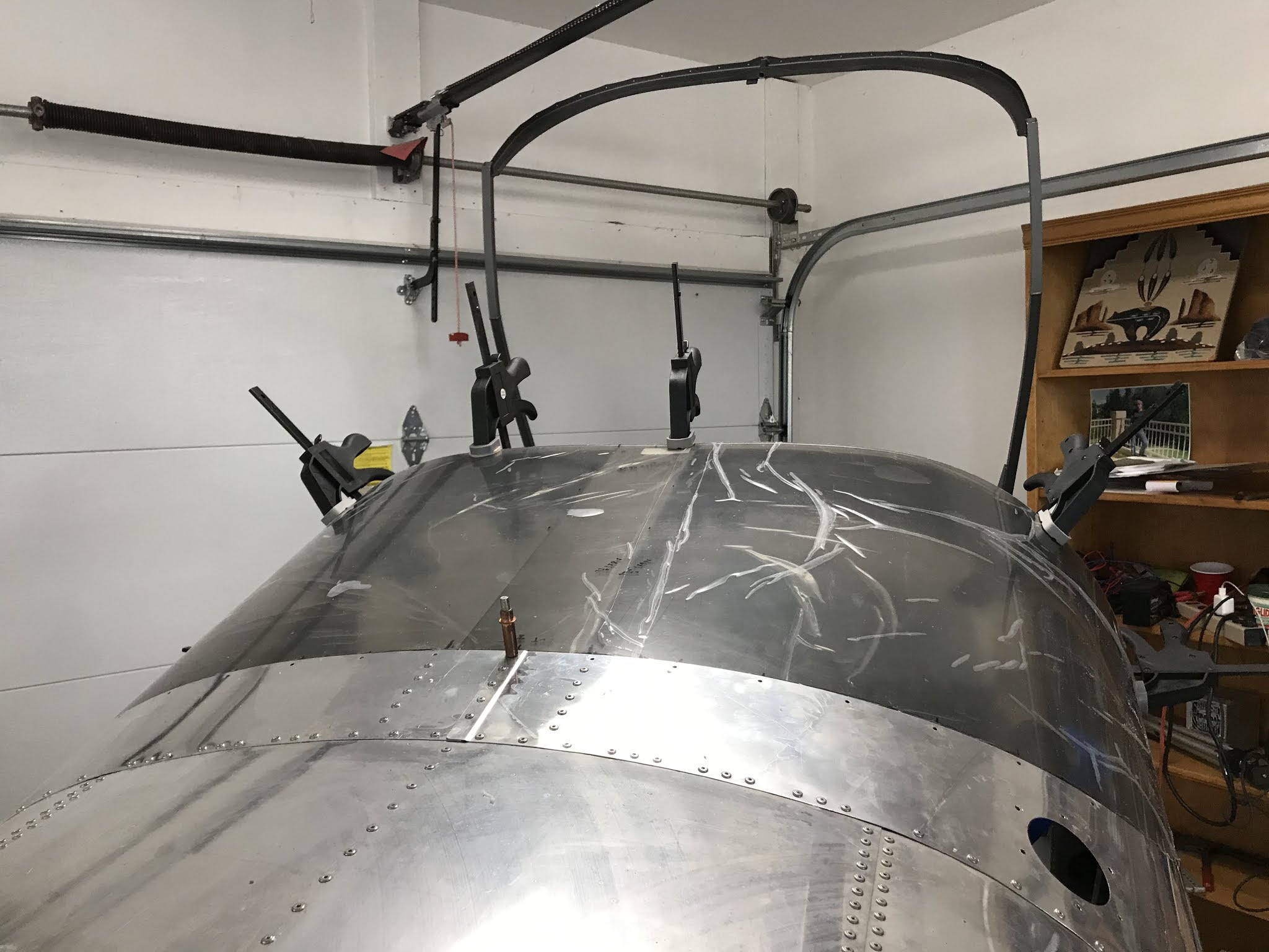
To set the tension for the stabilator cables, the control stick is positioned as shown using a fabricated 41-inch stick going from the back of the control stick to the longeron.  The front of the control stick
must be 10 inches from the panel.  The build manual is a bit vague here.  I assumed that, with the control stick in this position, both stabilator cables should be set to 35 lbf - 45 lbf as prescribed in the build manual and proceeded to do this.  I had erroneously assumed that this control stick position would cause the moments on the pulleys to cause the tensions in each cable to be equal.  Not so.


The tension is set using turnbuckles.  The cables themselves are prevented from rotating using the coat-hanger tool shown, while the turnbuckle is rotated, tensioning the cable.  This is done through the inspection holes in the bottom of the fuselage while lying on your back.  It's all trial-and-error:
Rotate the turnbuckle, crawl out from under the fuselage (a mechanic's creeper helps here), measure the tension, repeat.  Measuring the tension requires a tensionometer, which the build manual suggests can be borrowed.  The people who typically own these are A&P mechanics, who opined on Vansairforce.com that they would never lend these expensive tools out.  Can't blame them.  Since I'll have to check the tension yearly during the condition inspection, I bought one.


The repeatability of this instrument worried me a bit, but I finally set both cables to about (as close as I could read) 41 lbf.  The stabilator movement feels good and, after farting around with it for days, I declared it done.
After the cables are judged to be at the correct tension, the blue clips are installed (shown in the final pic).  The kit comes with four of these, so if you have to re-set tension after installing the clips, you're SOL.  They cost 8 cents each, so I ordered ten or so.  Right away, I needed them.

I don't feel great about this tensioning process.  They're set at 41 lbf, but if I pluck the stabilator cables, they rattle a bit in the bulkhead holes.  Several of these holes are not fitted with a grommet, and I'm guessing the cables shouldn't hit.  I may enlarge the holes a bit with a drum sander on a Dremel tool.  Normal operation of the stick seems fine.  My worry at this point is that installing the autopilot servos will affect the effort required to move the sticks.  I'll find out soon.

The blue clips are clearly shown in the final pic and require that a slot in the cable end line up with an internal slot in the barrel.  This whole tension process seemed a bit imprecise.

Monday, February 10, 2020

Page 32-05 Revisited: Control Stick Bushings


After installing the stabilator cables (post to follow) I spent some time moving the stick around and watching the stab move.  I could definitely feel play in the stick.  If I held one stick full forward, I could move the other stick about 1/16th inch at the top.  After trying to convince myself that "It
doesn't matter, I'll never even notice it while flying," I decided I couldn't accept it.  In my head I'm hearing the experienced builders whispering to me.  They're saying "Perfection is the enemy of flying your airplane."  I ignored the whispers.

In the picture at left, I have unbolted the stick and pushed out the bushing.  The bushing gets clamped tightly between the ears on the cross shaft, and relative motion occurs between the ID of the steel tube passing through the stick and the OD of the bushing.  For fore-and-aft motion of the stick (controlling pitch) I could feel the play, for lateral motion (roll) I could feel no play.  The problem arose when I originally reamed the ID of the steel tube.  The OD of the bushing from the factory was 0.375 inches (plus a bit) and wouldn't come close to passing through ID of the tube.  I lightly reamed the ID (using the red neck reamer shown -- a bolt with the head cut off and an axial slot which anchored a strip of #200 sandpaper).  I was able to borrow an actual 0.375 reamer and it passed easily through the tube.  Slightly
larger reamers were apparently, based on their prices, diamond coated and I couldn't afford to buy one for two passes through the tube followed by retirement to the reamer drawer in my toolbox.  The odd thing was that the bushing would pass 80% of the way through the tube starting from either end.  I decided the only way this could happen was if the ID of the steel tube was correct but the tube was very slightly bent in an axial direction.  Here's where I made the mistake: I reamed it a bit more until the bushing would go all the way through, then assembled everything.  This got me the end-to-end play when moving the stick fore and aft.

After determining that I couldn't stand the play, I had slightly oversized bushings made (thanks Joe), then carefully sanded the OD of the bushing into a slight hour glass shape (OD smaller in the middle).  Pilot's side is perfect, co-pilot's side still has slight play (I'll never fly from that side!).  The red neck lathe is shown (bushing held on a bolt which was chucked into my drill).