Wednesday, November 17, 2021

Instrument panel - autopilot knobs panel cutouts plus vinyl application

The first task required for prepping the instrument panel to actually receive instruments is to cut the holes for the two autopilot knobs panels.  The autopilot can be used without the panel, of course, but the common wisdom says that using the touchscreen on the Dynon Skyview HDX for all inputs is less than ideal.  It's much easier and more fun with actual knobs (especially in turbulence, I'm told).


Van's supplies a metal drill guide for locating and drilling the corners of the cutouts.  The rest involves cutting between the holes and filing the edges smooth.  The build manual suggests taping as shown to mark where the cuts go.  After drilling the 24 corner holes and mounting holes I used a straight edge and scribe to mark where the cuts would go but I suppose the tape makes it more visible.


The Van's site shows a part number for the center panel with the cutouts already there, but a call to them revealed that they never actually made it available.  

All the other cutouts and holes seen in the pic at right are already there.

I had received the right panel long ago and 1640 miles away when I was still in my ancestral stomping grounds of North Carolina.  The plans then called for all the holes in that panel to be counter sunk, which I did.  After making the decision to use faux carbon fiber vinyl wrap on the panel, I regretted that.  Turned out it didn't matter.  I have used black oxide button-head machine screws for the entire panel and, as the picture shows, they work just fine, even with counter-sunk holes.  The vinyl is 3M 2080 and, in my humble opinion, looks great.  I was so pleased with the wrap that I've decided to wrap the whole airplane.  Seriously.

If you click the pic to enlarge it, I think you'll agree.  The hardest part was getting the "weave" to line up at the panel edges, especially for the map box door.  I did the center and right panel with the aluminum pieces lying flat on a table.  For reasons I can't remember, I applied the wrap to the left panel after it was mounted in the airplane, resulting in a weave mismatch between the lower part of the left and center panels (visible in the next pic).  If I were doing it again I could do it perfectly (once again recalling the sage advice of those who have gone before: Perfection is the enemy of actually flying your airplane.


All instrument holes were cut out with an Exacto knife after the vinyl was applied, leaving about 1/2 inch extra to be wrapped around the hole edges.  A diagonal cut was made at each interior corner to allow wrapping.  All the screw holes were opened by spinning by hand a slightly larger bit in the hole.  The button-head screws conceal imperfections.


Sunday, June 6, 2021

Page 34-13: Making the fiberglass canopy skirt

Sometimes a made-up German phrase is required to adequately describe something: Yes, for the third time in the build, we have another Klöster Föken.

As I alluded to in the last post, I've dreaded the canopy fiberglass more than any other part of the build.  That dread was not misplaced.  The result of this section should be a fiberglass skirt attached to the Plexiglas canopy bubble and the aluminum pieces which are already attached to the bubble as described in the previous section.  The this section starts with two blocks of foam which must be shaped to conform to the curvature of the surrounding aluminum.  This is all done by eyeball.


The blocks must first be trimmed and drilled with a hole saw for access to the canopy pivot bolts which are already in place.  On the first drilling operation I managed to break off part of the foam, requiring that I fabricate out of scrap a new "nose" piece and epoxy it on (clearly seen on the left piece in the pic).


This is then epoxied to the existing aluminum structure and trimmed to match the existing curvature.  After shaping the first one entirely with 80-grit sandpaper attached to a block, I wised up and did the rough cut with a hack saw blade.


Shown below the piece being shaped is some scrap foam I inserted, later to be removed, to support the fiberglass which will hang down about 1/8th inch below the bottom of the temporary piece.


The pic at left shows the foam glued in place and shaped to match the surrounding curvature.  Three pieces of temporary foam are shown below the glued piece.  

Duct tape is applied everywhere the fiberglass skirt will contact the aluminum but should not adhere to it.  Packing tape is placed over the duct tape and a release agent is liberally smeared on this combo to allow the fiberglass to be removed.  I used Carnauba car wax.  Worked great.


The fiberglass cloth pieces will be cut to shape and applied to everything inside the duct tape and the red electrical tape which is applied to the Plexiglas and marks the bottom edge of the part of the Plexiglas which is to remain clear.  I used red electrical tape to contrast with the coming epoxy which I dyed black so it would look better from inside the airplane (thanks Dog Aviation!).  The green tape seen just below the red is inside the Plexiglas.


The pic at left clearly shows the aluminum piece shaped and installed in the previous post.  The coming fiberglass/epoxy will adhere itself to this, the foam block and the Plexiglas canopy below the red tape.  Because of the release agent (seen in the can sitting on the nose), the fiberglas/epoxy will lie against but not adhere to the aluminum covered by the duct tape.  Got it?

Now the bad part starts.


Five paper templates are supplied for cutting pieces of fiberglass cloth for each side, ten in all.  If you expand the picture at right you'll see cut lines on the paper.  The idea is to cut the outer piece of cloth, trim the paper template at the next inboard line, cut the cloth, repeat.

All cutting is done with a rotary knife against a smooth piece of plywood.


The fiberglass strips which bridge across between the side pieces are rectangular and of a specified width and length, eight pieces in all.

So far, so good.  Now the first piece of cloth, which was so carefully cut to shape, is to be placed on a piece of plastic cooking wrap and wetted out with epoxy. I used West System epoxy.  Some experts (not being sarcastic here -- these people truly are experts) advise against using the pumps to dispense the epoxy in proper proportions and suggest that weighing the epoxy is best.  Using a postal scale for this caused me to have little confidence in this method, probably because of poor technique on my part. The pumps were quick, easy, and seemed to work perfectly.  I love the pumps.


After carefully cutting the first, largest piece of cloth to shape I transferred it to the cooking wrap, whereupon its shape immediately changed from what it should have been into something that resembled the state of Texas.  No amount of tugging would transform it back into the shape of the template.  I did the best I could, brushed on the epoxy, squeegeed out all the excess and transferred it to the canopy.  I had marked the area it was supposed to cover and it was nowhere close.  Each subsequent piece of cloth is placed dry on the previous, still tacky piece of cloth and wetted out using a brush.  The picture at right shows all five pieces of cloth/epoxy in place.  I showed the right side because, as bad as it looks, it was way better than the left side (the first one I did).  The strips bridging left and right were then done in a particular order and position. 


Then the fun begins.  Supposedly, the good thing about fiberglass is that if you (word redacted due to the family nature of this blog) it up, you simply sand away the bad part and re-do it.  This was my saving grace.  If you look at EweTube (they're a bunch of sheep) videos showing this process it all comes out near perfect after the first layup.  Mine came out looking like the surface of the moon.  Small fiberglass patches can be glassed into the low spots and high spots can be sanded down.  Every time you glass something it needs at least 24 hours to cure before sanding, depending on the temperature in the hangar.  This takes a while.  Here in Colorado while I was doing the fiberglassing the OAT was sometimes below 20 F.  My gas heater could only get the temperature in the hangar up to about 52 F on the coldest days.

The radius of curvature for the intersection of the Plexiglas and the aluminum is supposed to be 2 inches.  I discovered that the O.D. of a 3-inch PVC coupling is 4 inches.  Perfect.  


After quite a few iterations of glassing and sanding it looked like this.  The lighter colored area is un-dyed epoxy.  I only dyed the lowest layer but on subsequent layers the black dye bled through.  The idea behind having the upper layers clear was to make it easy to know when you've sanded through to the lowest layer.  Didn't work.


Small low spots can be filled with a mixture of micro-balloons (tiny spheres of glass) and epoxy, usually just called micro.  Dry micro refers to a mixture that has the consistency of peanut butter.  This stuff can be slathered on and easily sanded.  I should have used it earlier.

I trimmed a tongue depressor so that it had the 2-inch radius and a straight section to gage the shape as I sanded.


At this point I decided to raise the canopy and remove it from the airplane, finishing the rest of the sanding on the workbench.  This required that I locate and drill out the holes for the canopy pivot bolts, having covered them with fiberglass earlier.  I did this by looking at the plans and triangulating from known rivet locations, then drilling with a small bit where I thought the center of the pivot bolt was.  The hole in the fiberglass was then opened to the correct dimeter with a sending drum.  I used a putty knife as shown to break the fiberglass free from the tape with release coat.  At this point I inclined my head a few degrees and said a silent prayer.  The canopy popped right up.


I trimmed to essentially the final shape on the work bench.  I am quite pleased with how thin and stiff the fiberglass turned out.  Several of the RV-12s I saw at Oshkosh had, in my opinion, excessive thickness here.

The idea with the black dye for the epoxy didn't work out so well but was probably worth doing.  I had to spray the inside of the fiberglass black.


If I were a better craftsman I'd no doubt do a few more iterations of the micro/sand loop.  Since I'm sick of fiberglass dust, I sprayed a high-build primer on and sanded that.  Considering what an absolute PITA this part has been, I'm fairly happy with the result.


Re-installing the canopy, I had the Spousal Unit slowly raise it while I observed the substantial interference above and forward of the pivot bolt.  I marked and trimmed it as shown.


Trimming with a file was done on the back side of the fiberglass.  The second, larger scollop was done to expose the aft-most screw just above the fiberglass.  This is the configuration on the original plans I received.  On current plans only the smaller scollop just above the pivot bolt is shown.  Doing it this way would require removing the canopy in order to remove the covering over the instrument bay.  That's the aluminum forward of the fiberglass.  No thanks.

As I said before, considering what a PITA this was and how much I complained about it, I'm happy with the result.  The fit against the aluminum is good.


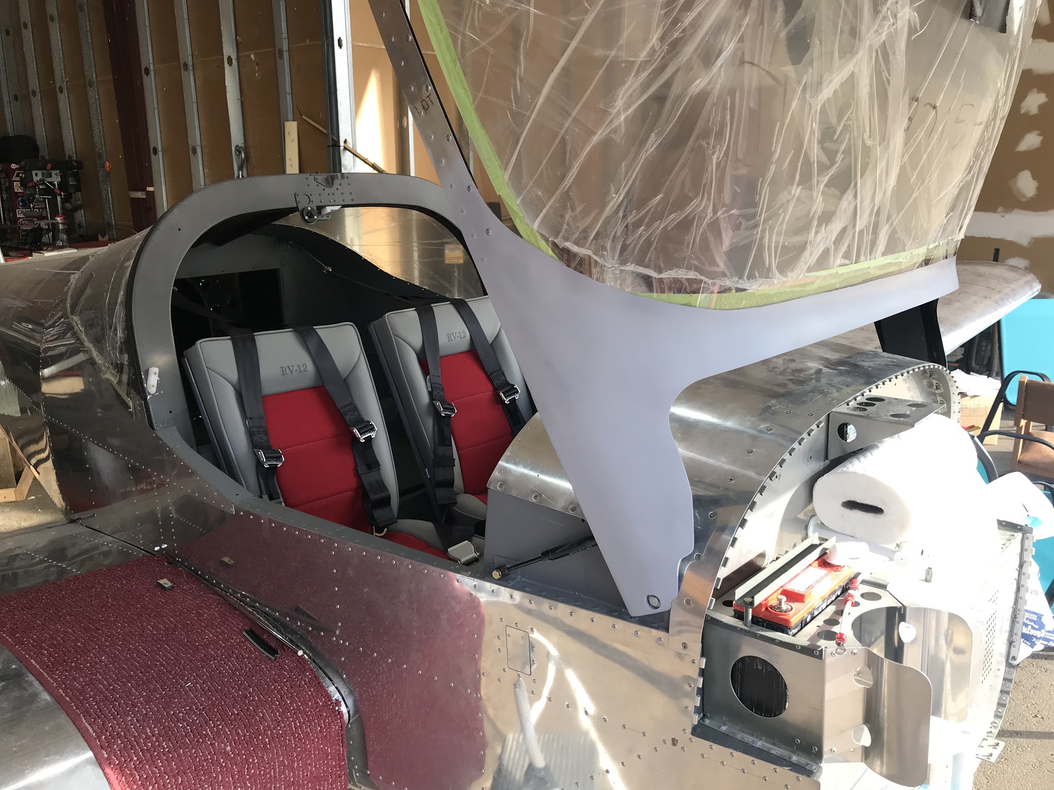
I installed the upholstery and five-point harnesses just to make myself feel like I'm approaching having a real airplane.  Yes, I closed the canopy, strapped in and pretended to fly.😎


A few canopy seals remain to be installed, then on to the engine!  The avionics kit has been ordered, so no more big cash outlays.

Sunday, January 10, 2021

Page 34-01: Trimming the canopy to fit the frame, then attaching the canopy to the frame (fiberglass to follow in another post)

The bare canopy frame comes with the kit, welded and ready to receive various add-on bits required for attachment of the plexiglass canopy.  The frame consists of a "front bow" and a "rear bow" connected by

some tubing of rectangular cross section, with an aluminum plate at the forward end which contains a hole for the pivot point and a second hole for attachment of the air springs.  The air springs take part of the load required to open and close the whole thing once everything is attached.  I had erroneously assumed that the canopy, like the rear window, would be essentially the right size, needing only to be correctly positioned and drilled, then riveted/screwed to the frame.  Alas, this was not the case.

After the pivot bolts are installed, the rear bow is clamped to the roll bar with spacer blocks between them, assuring the frame is positioned correctly.  At this point there should be 1/8th inch between the rectangular tubes and the fuselage rails.  Not close.  The build manual suggests taping strips of corrugated cardboard, as found in typical cardboard boxes, to the tops of the fuselage rails to provide this gap.  The problem was that when the frame was clamped into place, a compressive load was put on the cardboard, causing its thickness to be reduced.  The angle between the two welded-together pieces of rectangular tubing needed to be altered.

At this point, I made the lucky discovery that the little wooden paint mixing sticks which you're given when you buy paint at Lowe's or Home Depot are exactly 1/8th inch thick and won't be compressed by the frame.  With the pivot bolts installed and a small block of wood positioned under the weld (which can be seen in the pic as a vertical line joining two straight sections of rectangular tubing), I put my weight on the rear bow and bent the tubing at the weld.  Got it right the first time!  The frame fit like a charm, verified by little pieces of paint stirrer sticks placed all along the interface between the rectangular tubing and the fuselage rails.  Now just pop the canopy in and drill baby, drill!  Uh, no.

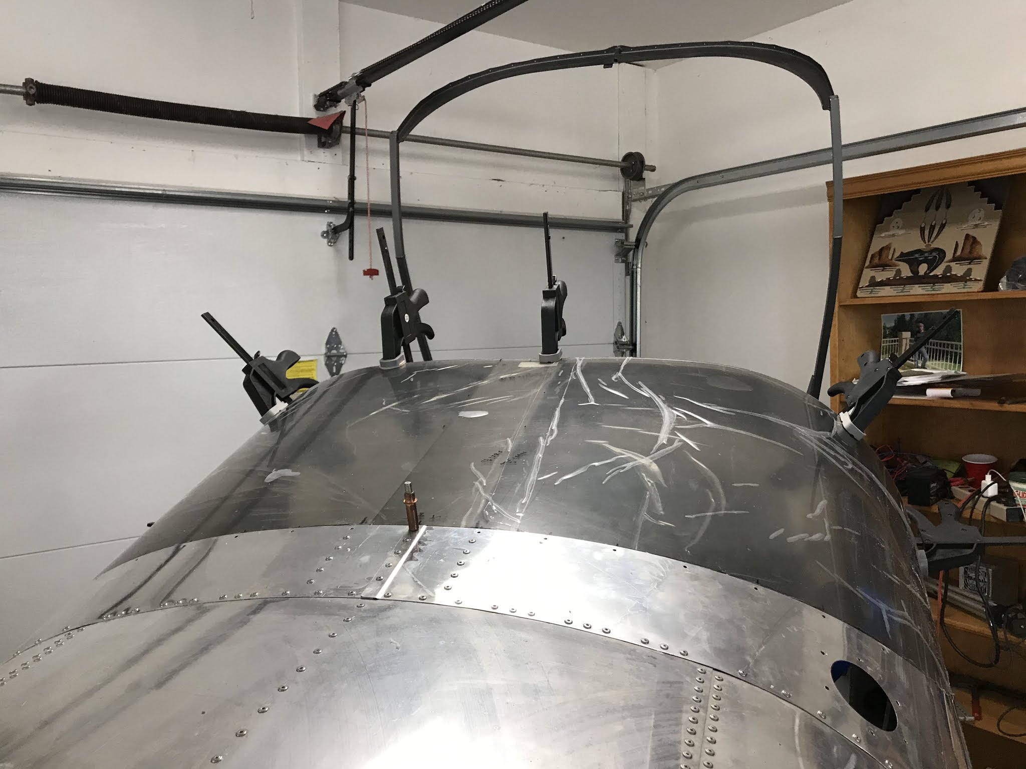
The canopy is supposed to have 1/8th inch clearance between the forward edge and the plane of the instrument panel and 1/8th inch clearance between the bottom edge and the canopy frame.  The build manual says to trim the aft edge to produce 1/32nd inch clearance between it and the rear window.  This is the only mention of trimming the canopy.  Clamping the canopy in place, these dimensions could not be achieved.  I wasted countless hours repositioning the canopy and re-clamping.  Couldn't be done.  I finally decided to trim the bottom edge even though no mention of this is made.  Bingo!  After many iterations of install-measure-remove-trim, it finally fit.  I was worried that having the canopy frame held to shape by the canopy would unnecessarily stress canopy, promoting cracking.  

The drilling was uneventful (this time -- see rear window post).  After clekoing the now-well-fitting canopy in place, I discovered that the canopy and frame wouldn't pivot open, requiring further trimming of the forward edge (goodbye 1/8th inch clearance!).  This doesn't matter at all since it will all be covered with the fiberglass skirt (post to follow).

Also in this section of the manual is the fabrication and installation of the canopy latch.  This involves shaping the exterior part of the handle (which I did by eye using a belt sander and Scotch-Brite wheel)


and attaching it to the shaft connected to the interior part of the handle.  The parts must be carefully aligned and drilled.  I found this difficult even though I fixtured it as best I could on the drill press, ending up with a definite angle between them.  The interior handle must be fore-and-aft in order to properly engage the latch, meaning the part out in the 150 mph slipstream (yeah, I'm an optimist) will be at a small angle of attack, causing drag.  Being an aero guy, this was unacceptable. 

My fix was to carefully elongate the hole in the shaft until alignment was perfect, fill the shaft with a mixture of epoxy and flox, and re-drill with the two parts assembled.  The screw holding all this together is tapped into the aft portion of the handle.  I coated the portion of the shaft which is inside the handle with wax so the epoxy wouldn't stick.  Everything is working well.  Opening and closing the canopy requires significant torque on the shaft.  If some play develops there over time, I'll remake the part.


Friday, December 25, 2020

Let there be light (and heat)

A southern boy tries to survive his first full winter in Colorado 

Although we've had this house in Colorado for about five years, we've mostly spent summers here with a bit of fall and spring thrown in.  This first full winter as a hangar owner quickly showed me that working on a metal airplane in really cold weather is difficult.  I used my "salamander" heater more than I should have (it says right there on the heater "Do not use in enclosed spaces") figuring that the hangar was leaky enough that I was safe breathing the products of combustion if they were somewhat diluted.  I finally bit

the bullet and had sprayed-in foam applied to the ceiling and door, and since I was already hemorrhaging money I bought and installed a Mr. Heater 80,000 BTU/hr gas heater.  To be truthful, my hangar neighbors (thanks Chad and Tom) did essentially all the work running the gas line, installing the meter and heater, running the wiring and since the were already up there, installing three more super-bright LED ceiling lights for a total of four (brand name is UFO Deformable, 7200 lumens, 6000K color temperature, $24 each on Amazon).  I believe they were concerned that a person my age shouldn't be 18 feet in the air doing that stuff -- looks like my feeble old man act worked.  I did run the conduit and wire around the walls to install 20 new electrical outlets, allowing me to make the fire inspector happier by getting rid of all the extension cords.

The picture shows the heater mounted at the ceiling, and you can also see the blown-in foam (R-28) which looks like Mammatus Clouds (my favorite kind).  The insulation on the bi-fold door looks the same but in a vertical plane.  All that's lacking is the centrally located ceiling fan, which I bought and assembled today.  This should cure the current situation where all the hot air stays at the ceiling while the air below stays about 55 F.  Even with the stratification, it's a huge improvement.  Next comes the fiberglass part of the canopy.  All the endless trimming and trial fitting of the canopy is finished (blog post to follow).

Since we're talking about the future, the engine kit has arrived!  Here's what $30,000 will get you these days:

Engine, prop, ducts, hoses, wires, everything forward of the firewall, causing my wallet to be much lighter.  The good news is that this is the next-to-last kit.  I'll order the avionics kit as soon as I settle on which bank to rob.  Using dollars per cubic meter as a metric, that box will win by a long shot.

Thursday, September 10, 2020

Page 25A: Installing the Plexiglas rear window -- an expensive tale of woe

 Note: This work occurred back in North Carolina, before the big move to Colorado, so we're a bit out of chronological order.

The kit as I ordered it came with a Lexan rear window (still in its protective plastic back in NC -- one of many parts paid for but not used) which was subject to crazing when exposed to even the smallest amount of gasoline.  The location of the fuel filler made it almost impossible to avoid this fate, so the Mothership came out with a replacement made of plexiglass (Plexiglas) which solved the problem.  Naturally, I ordered this, never missing an opportunity to spend even more money.


The first step in the installation called for carefully positioning the window fore and aft as well as side to side before drilling the first hole, after which further position adjustments were impossible.  I spent countless hours on this step, which makes what happened hurt even worse.  After clamping the window to the roll bar, I drilled that hole.  You can see the cleco center aft in the first two pictures.  Getting the window into this position required lots of fiddling.

The window fits over the roll bar at the forward edge but under the tail cone skin at the aft edge, meaning there's nothing to hold the Plexiglas against the inside of the aluminum skin.  To solve this problem I fabricated two flexible braces from PVC (shown in the pic).  With the plexi held firm, I felt confident in the final measurements, ensuring a good fit.  

Having to repeatedly clamp and unclamp the forward edge while repositioning the aft edge and taking measurements all around proved to be challenging.  I wasted a lot of time here.

To safely drill or cut plexi without fear of cracking, the temperature should be above 70 F, easy to do in NC in the spring.


In order to match drill the holes in the unsupported plexi along the aft and bottom edges, a helper was needed to hold a block of wood firmly against the inside of the plexi while the hole was drilled from the outside.  The Spousal Unit (a.k.a. Dr. KTH) was pressed into service for this task.  Her ghostly image can be seen through the protective plastic sheet covering covering the window.

The sequence for this drilling is specified in the build manual. Certain #30 holes are matched drilled through the aluminum skin alternating with certain #40 holes through the window and roll bar.  Clecos are inserted after drilling each hole.  Everything looked good.  Little did I know.

Then came the bad part.  Each #40 hole through the plexi and roll bar (thick aluminum) is to be enlarged to #36 with a reamer then tapped 6-32 and the appropriate screw inserted.  All holes, including the tapped ones, are to be enlarged to #27 later.  This is very unclear in the instructions and many builders didn't enlarge the tapped holes.  I started on the lower right side tapping the holes and had made it though about 75% of them when the tap shattered, cracking the window ($500).  I was using best practices, backing the tap out to clear chips every turn.  From the start it seemed that the tap was requiring an uncomfortable amount of torque going through the aluminum and plexi at the same time. If I had it to do over, I'd go straight to the #36 bit, skipping the #40, and I wouldn't tap the plexi.  All drilling of the plexi was done with bits made for this purpose and all enlarging of holes was done with a reamer or a UniBit (step drill).

After removing the window, I tapped the remaining #36 holes in the roll bar (very low torque required) and ordered a new window.  I was now faced with figuring out how to drill the roll-bar holes in the new window and make make them line up with the already-drilled-and-tapped holes.

Now extremely gun shy about working with Plexiglas, I repeated the whole process (complete with Spousal Unit inside), but eyeballed where to drill the #40 holes so that they were concentric with the existing tapped holes, not wanting to damage the existing threads.  My thinking was that enlarging the holes in the plexi later to #27 (as called for) or 5/32 (if needed) would handle any eccentricity.

The pic shows the #30 holes clecoed and the screws placed in the roll bar.  The tape around the lower and rear borders is positioned 1/32 inch (eyeballed!) from the aluminum to limit where the ProSeal goes in the final installation.  I'll wait until much later in the build to permanently attach it.  The tape on the forward edge of the canopy marks the line to which the plexi is to be trimmed, lining the leading edge up with aft edge of the forward half of the roll bar.  The trimming was done with a cabinet makers scraper.  Plexi responds well to scraping but poorly to cutting, explaining why a reamer or UniBit is ideal.  I wish UniBits came in number sizes.


Saturday, June 20, 2020

Moving the project to Colorado

When I started this build 9 years ago, with my usual hubris it never crossed my mind that I wouldn't finish the airplane in North Carolina and fly it to Colorado where it would be based for the duration.  Years dragged by with progress which could sometimes be characterized as glacial, so I found myself retired (after teaching Mechanical Engineering at UNC Charlotte for 34 years) with the spousal unit accepting a faculty position in the Mechanical Engineering department at Colorado State University.
 After much soul searching I decided to do what I recently swore I'd never do: move the project by truck across the country.  Reading other peoples' blogs, it seemed that most people did it themselves.  My best estimate on the cost of renting a 22-foot truck and paying for the Diesel fuel was $1600 (probably low).  I discovered Stewart Transport, who specializes in moving light aircraft, and found their quote to be $2500.  This $900 delta turned out to be some of the best money I've spent.  Shelly and Mark showed up in the most impressive 18-wheeler I've ever seen, outfitted with a special crane for loading the fuselage, with the wings being strapped to the walls in padded slings.  This was much better than I had envisioned doing it myself and it was definitely a good thing it was done so well: winds through Kansas and Colorado were consistently gusting to 40 mph (direct cross wind), forcing many 18-wheelers to park for a while.  I don't want to even think about me in a lightly-loaded truck having to deal with that.

The Mothership recommended that I build a false spar made of 1-inch plywood with holes for the spar pins and holes for tie down purposes (these weren't used).  The crane attached to this and the nose wheel strut.  Worked perfectly.

After loading, my two dogs and I raced the truck to Colorado -- barely beating them -- where we unloaded at my new hangar.  Feels great to utter those words: my new hangar.  I had been on a wait list for a hangar both in North Carolina and Colorado for many years, making no apparent progress toward a rental unit.  After checking prices on purchasing a hangar I put that out of my mind.  Then, out of the blue, I got a personal message on Vansairforce.com (thanks, Ken) about the availability of a T-hangar at KLMO (1.5 miles from my house) for $40k, almost too good to be true (it even has an electrically operated door!).  Of course, that's part of the money I needed to buy the firewall-forward kit and the avionics kit, but that's another story.  KLMO is a hotbed of experimental aircraft activity, with lots of RVs including two other RV-12s.

In a previous post I bragged that I'd built the fiberglass tailcone fairings without removing the stabilator.  I went on to say that I'd fly the airplane having installed the stabilator (an odious task) only once.  So much for that.  It had to come off to fit in the truck.  I constructed a stand just the proper height to support the stabilator while removing the two 1/4-inch bolts (kinda scary) which hold it on the airplane.  The bolts can then be accessed with an 8-inch extension connected to the 7/16th socket with a universal joint, allowing for the required misalignment.  A big contributor to making the process a PITA is the lead counterweight which sticks a couple of feet into the tailcone.  The shaft holding it, the aft end of which is seen in the picture, must be unbolted and rotated 90 degrees to fit through the hole in the aft-most bulkhead in order to be withdrawn, an awkward process for one person.  The most maddening thing, however, is having to remove the tension from the stabilator cables (see previous post) only to redo it upon arrival in Colorado.  Here it is in its new home.
                                                     
The sequence of events which lead to this massive relocation from my ancestral home in the South to my new home in Colorado almost seems preordained.  Every piece of the puzzle fell into place without any effort.  If I were religious or otherwise mystical I'd attribute it to some power beyond my understanding.  Alas, I must attribute it to happenstance: the spousal unit (my beautiful and talented wife, Karen) became interested in triathlon, attended Dave Scott's triathlon camp in Boulder, spent the following summer training with him and completing the Boulder IronMan two summers in a row, by chance trained with the number one real estate guy in Boulder (thanks Sasha) who put us onto an amazing house in Longmont, was able to teach summers at CU Boulder, then got a faculty position at CSU.  Every piece of the puzzle fell neatly into place.  I'm still amazed by it all.


Monday, March 2, 2020

Page 44: Autopilot servos

Considering that I want to get everything that goes beneath the seats and baggage compartment panels installed in preparation for closing all that up, the time had come to make a fairly big decision: Garmin or Dynon autopilot?  I had intuitively been leaning toward Dynon rather than the 800-pound
gorilla.  Not sure why.  I knew that Dynon map updates were free for life, but a visit to Mothership's website which shows the cost of all the bits and pieces I'm going to have to buy sealed the deal.  For the single display (can't afford dual), autopilot servos, knobs panel (optional but makes setting the autopilot easier in flight), ADSB in and ADSB out, the Dynon was about $2500 cheaper.  With all the other stuff in the avionics kit (radio, intercom, etc.) the total cost for the Dynon is $18,995.  A staggering amount of money for a guy about to retire, but I have no choice.


The title of the picture above is "Two Autopilot Servos and a Meat Servo."  Each AP servo -- one in each hand -- costs over $800.  The meat servo between them is the chump footing the bill.  You can see that I've installed the canopy frame.  The rear window is hugging the tail cone, waiting for a trial fit.


One of the first steps involves stripping all the wires from the two servos, 14 wires in all, and crimping a .093 Molex pin on each.  A good crimp tool is a must for this, but even with the best available from Klein Tools I managed to screw up a few and had to re-order.  The stripper from Klein (shown) is also well worth the money.


There's definitely a technique involved in making the crimps.  There are two sets of tabs involved,
with the outer set making a bear hug on the insulator and the inner set plunging into the conductor.  After each crimp, I gave the Molex pin a fairly hard pull.  A few failed the test and had to be re-done.  The picture shows an average crimp.

When each seven-wire set is crimped, the pins have to be inserted into a 9-position Molex connector which will plug into an opposite gender plug installed much earlier in the build during the wiring harness installation.  Each pin must go into the correct hole in the connector, of course, and there's a very clear diagram to help facilitate this.  After doing it correctly, I gave one last tug and one of the wires came out!  This required removing an already-inserted Molex pin from the connector, which is an odious task.  Quite a few swear words followed this event.


Installation of the servo motors was fairly straight forward.  I was immediately able to allay my previously mentioned fears about the effort required to operate the control stick with all the AP hardware installed.  You can feel some added resistance to movement, but not much.


Pic above shows roll servo, pic below shows pitch servo.