Monday, March 2, 2020

Page 44: Autopilot servos

Considering that I want to get everything that goes beneath the seats and baggage compartment panels installed in preparation for closing all that up, the time had come to make a fairly big decision: Garmin or Dynon autopilot?  I had intuitively been leaning toward Dynon rather than the 800-pound
gorilla.  Not sure why.  I knew that Dynon map updates were free for life, but a visit to Mothership's website which shows the cost of all the bits and pieces I'm going to have to buy sealed the deal.  For the single display (can't afford dual), autopilot servos, knobs panel (optional but makes setting the autopilot easier in flight), ADSB in and ADSB out, the Dynon was about $2500 cheaper.  With all the other stuff in the avionics kit (radio, intercom, etc.) the total cost for the Dynon is $18,995.  A staggering amount of money for a guy about to retire, but I have no choice.


The title of the picture above is "Two Autopilot Servos and a Meat Servo."  Each AP servo -- one in each hand -- costs over $800.  The meat servo between them is the chump footing the bill.  You can see that I've installed the canopy frame.  The rear window is hugging the tail cone, waiting for a trial fit.


One of the first steps involves stripping all the wires from the two servos, 14 wires in all, and crimping a .093 Molex pin on each.  A good crimp tool is a must for this, but even with the best available from Klein Tools I managed to screw up a few and had to re-order.  The stripper from Klein (shown) is also well worth the money.


There's definitely a technique involved in making the crimps.  There are two sets of tabs involved,
with the outer set making a bear hug on the insulator and the inner set plunging into the conductor.  After each crimp, I gave the Molex pin a fairly hard pull.  A few failed the test and had to be re-done.  The picture shows an average crimp.

When each seven-wire set is crimped, the pins have to be inserted into a 9-position Molex connector which will plug into an opposite gender plug installed much earlier in the build during the wiring harness installation.  Each pin must go into the correct hole in the connector, of course, and there's a very clear diagram to help facilitate this.  After doing it correctly, I gave one last tug and one of the wires came out!  This required removing an already-inserted Molex pin from the connector, which is an odious task.  Quite a few swear words followed this event.


Installation of the servo motors was fairly straight forward.  I was immediately able to allay my previously mentioned fears about the effort required to operate the control stick with all the AP hardware installed.  You can feel some added resistance to movement, but not much.


Pic above shows roll servo, pic below shows pitch servo.

Saturday, February 15, 2020

Page 32-11: Installing and tensioning cables

I built the wooden structure for positioning the rudder pedals for cable installation out of scrap wood, then hooked up the rudder cables.  The cables are pulled through the tail cone using strings taped in there much earlier in the build.  This pulls them through all the bushings, ready to attach to the
stabilator.  Easy, if I hadn't managed to let one of them fall back into the tail cone (twice).  I had to make a long, skinny, flexible piece of wood, push it through the tail cone and all the bushings, then re-pull the string.


In the pic below you can see the forward attach point for the rudder cables, and the cables passing through the bushings in the forward-most bulkhead.  These cables have zero tension until feet press
the rudder pedals.  The control sticks appear to not be parallel due to the short focal length of the lens in my iPhone.  They're parallel to within a degree or so.  I tried to convince myself that the sticks should be canted inward a bit, making a more natural-feeling wrist angle, but didn't like to look.

The seat ramp cover is removed in this pic, but had to be re-installed before tensioning the stabilator cables to prevent a slight distortion of the structure due to the tension.


The pic at right shows the cables attached to the rudder.  Here's where I accidentally let the cables slip back through the holes while I was trying to get the correct washers in and lined up before bolt insertion.

Steel straps are fabricated to set the correct length of the cables when they're attached to the rudder.  These attach at the front end of the cables.


To set the tension for the stabilator cables, the control stick is positioned as shown using a fabricated 41-inch stick going from the back of the control stick to the longeron.  The front of the control stick
must be 10 inches from the panel.  The build manual is a bit vague here.  I assumed that, with the control stick in this position, both stabilator cables should be set to 35 lbf - 45 lbf as prescribed in the build manual and proceeded to do this.  I had erroneously assumed that this control stick position would cause the moments on the pulleys to cause the tensions in each cable to be equal.  Not so.


The tension is set using turnbuckles.  The cables themselves are prevented from rotating using the coat-hanger tool shown, while the turnbuckle is rotated, tensioning the cable.  This is done through the inspection holes in the bottom of the fuselage while lying on your back.  It's all trial-and-error:
Rotate the turnbuckle, crawl out from under the fuselage (a mechanic's creeper helps here), measure the tension, repeat.  Measuring the tension requires a tensionometer, which the build manual suggests can be borrowed.  The people who typically own these are A&P mechanics, who opined on Vansairforce.com that they would never lend these expensive tools out.  Can't blame them.  Since I'll have to check the tension yearly during the condition inspection, I bought one.


The repeatability of this instrument worried me a bit, but I finally set both cables to about (as close as I could read) 41 lbf.  The stabilator movement feels good and, after farting around with it for days, I declared it done.
After the cables are judged to be at the correct tension, the blue clips are installed (shown in the final pic).  The kit comes with four of these, so if you have to re-set tension after installing the clips, you're SOL.  They cost 8 cents each, so I ordered ten or so.  Right away, I needed them.

I don't feel great about this tensioning process.  They're set at 41 lbf, but if I pluck the stabilator cables, they rattle a bit in the bulkhead holes.  Several of these holes are not fitted with a grommet, and I'm guessing the cables shouldn't hit.  I may enlarge the holes a bit with a drum sander on a Dremel tool.  Normal operation of the stick seems fine.  My worry at this point is that installing the autopilot servos will affect the effort required to move the sticks.  I'll find out soon.

The blue clips are clearly shown in the final pic and require that a slot in the cable end line up with an internal slot in the barrel.  This whole tension process seemed a bit imprecise.

Monday, February 10, 2020

Page 32-05 Revisited: Control Stick Bushings


After installing the stabilator cables (post to follow) I spent some time moving the stick around and watching the stab move.  I could definitely feel play in the stick.  If I held one stick full forward, I could move the other stick about 1/16th inch at the top.  After trying to convince myself that "It
doesn't matter, I'll never even notice it while flying," I decided I couldn't accept it.  In my head I'm hearing the experienced builders whispering to me.  They're saying "Perfection is the enemy of flying your airplane."  I ignored the whispers.

In the picture at left, I have unbolted the stick and pushed out the bushing.  The bushing gets clamped tightly between the ears on the cross shaft, and relative motion occurs between the ID of the steel tube passing through the stick and the OD of the bushing.  For fore-and-aft motion of the stick (controlling pitch) I could feel the play, for lateral motion (roll) I could feel no play.  The problem arose when I originally reamed the ID of the steel tube.  The OD of the bushing from the factory was 0.375 inches (plus a bit) and wouldn't come close to passing through ID of the tube.  I lightly reamed the ID (using the red neck reamer shown -- a bolt with the head cut off and an axial slot which anchored a strip of #200 sandpaper).  I was able to borrow an actual 0.375 reamer and it passed easily through the tube.  Slightly
larger reamers were apparently, based on their prices, diamond coated and I couldn't afford to buy one for two passes through the tube followed by retirement to the reamer drawer in my toolbox.  The odd thing was that the bushing would pass 80% of the way through the tube starting from either end.  I decided the only way this could happen was if the ID of the steel tube was correct but the tube was very slightly bent in an axial direction.  Here's where I made the mistake: I reamed it a bit more until the bushing would go all the way through, then assembled everything.  This got me the end-to-end play when moving the stick fore and aft.

After determining that I couldn't stand the play, I had slightly oversized bushings made (thanks Joe), then carefully sanded the OD of the bushing into a slight hour glass shape (OD smaller in the middle).  Pilot's side is perfect, co-pilot's side still has slight play (I'll never fly from that side!).  The red neck lathe is shown (bushing held on a bolt which was chucked into my drill).

Sunday, December 1, 2019

Page 12-05: Tail cone fiberglass fairing -- third on the list of least-fun parts of the build

First the good news: It can be done well without removing the stabilator.  The previous section in the build manual had the builder (me) install the stabilator, a royal PITA to be sure.  I'd been itching to install all the tail feathers anyway, so after double-checking that I could get the airplane through the garage door with everything on (except the wings), I did it without reading the next section (yeah, I know, read ahead).


The vertical stab was easy even though it required a crow's foot on the torque wrench for a couple of bolts.  Gotta be at a 90 degree angle to the wrench (as shown) to read correctly.  Otherwise, some cipherin' is involved (to quote Jethro Bodine).


Bolting the stabilator on required that everything be at the correct height for the bolt holes to align, easier said than done.  It can't simply be held in the right position, even if I'd had a helper, because it's too ungainly with no easy hand holds.  I built a U-shaped structure from 2x4s and other wood scraps to support it and finally wrestled it into position.  I guess having two helpers would make it work.


Part of the problem with the stabilator attachment is getting the washers into position while inserting the bolts.  This was made much easier with a product called Washer Wrenches.  If I'd had these things for the entire build I'd probably have more hair left on my head.


With the vertical stab, stabilator, anti-servo tab and trim motor installed I turned to page 12-05 only to discover that it was assumed that the stabilator was back off the airplane.  In fact, as per the procedure laid out in the build manual, the stabilator has to be installed and removed several times to carry out all the trial fitting and trimming required for a good fit.


This is all necessitated by the build manual calling for the slot for the anti-servo tab actuator rod to be delayed until near the end of the section, making it impossible to remove the fairing with the trim motor in place.  I decided to cut the slot early, which allowed the whole thing to happen with the stabilator in place.  In fact, I plan to fly the airplane having installed the stabilator only once.


I cut the slot, taped a 3/4 inch piece of wood in place to provide the needed rigidity, and ended up with a good fit.

According to the build manual, drilling for the nut plates which hold the fiberglass fairing to the aluminum tail cone is to be done from the inside out using a long, flexible drill bit.  I couldn't make this work, even with my Tight-Fit Drill Kit, shown below, which has bailed me out of tight situations on numerous occasions.  As small as the head on this thing is, it still couldn't put the bit at right angles to the surface.


Instead, I made a drill template consisting of a curved piece of aluminum (below) representing the curve and thickness of the actual tail cone.  With this I attached the nut plates and drilled from the inside out through the nut plate rivet holes, the tail cone stand-in and the template.  With this template I drilled from the outside in through the tail cone.  Worked perfectly.  Even if I'd had the stabilator off, I couldn't have done it inside-out.


The whole thing required a lot of trial fitting and trimming/sanding.  I used a Dremel tool with a cutoff wheel or sanding drum for most of it.


I started out using a cartridge-style mask but discovered that I was ingesting a lot of fiberglass dust, probably because my facial hair prevented a good seal.  I finally resorted to my red-neck respirator (below) which involves a long hose with a mouth piece from a snorkel: breath in through the mouth and out through the nose.  It's the only thing that works well.


The tabs which connect the two pieces of the fairing together (below) are first match-drilled through the fiberglass while positioned on the outside, then switched to the inside for riveting.  Setting solid rivets in fiberglass made me a bit nervous but it turned out OK.


The bad part of this section is all the sanding of fiberglass and endless trial fitting.  When I over-sanded a seam, I filled the gap using a product called Bondic (cheap at Lowe's) which was developed
for filling teeth.  It's some sort of hard plastic which cures using a UV light (included) in a matter of seconds and can be sanded immediately.  There must be many other uses for this stuff.


A part unrelated to the tail cone fairing showed up today: four little plastic plugs which fit into the open ends of the boarding steps, lowering the drag a bit.  I have no comment about these parts.😬

Friday, October 25, 2019

Page 37: Fuel tank -- There's gotta be a better way

The tank is made up of four large pieces of aluminum sheet which comprise the walls, plus lots of other bits and pieces -- structural stuff which goes on the outside and various baffles which go inside. All of this has to be riveted together with different rivet types plus a few machine screws.
There are a couple of hundred rivets providing a couple of hundred sites for potential fuel leaks.

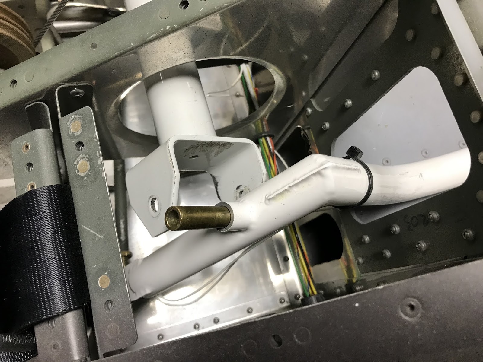
The piece shown at left (one marked scrap that I screwed up and the replacement) has seven different kinds of rivets or machine screws, some counter sunk, some not.  It's a beefy piece supporting two of the three bolts which actually attach the tank to the airplane.  The bolts are frangible (hollow) designed to shear in a crash or super-hard landing so the tank won't distort and spill fuel in the cockpit (something which could ruin your whole day).  All the rivets in this piece, along with all the rest, pierce the inside of the tank (leak possibilities).

Here's the bad thing about all these rivets: Each one has to be washed in naphtha and coated with ProSeal before being set.  ProSeal has a working life of two hours from the time it's mixed with the
catalyst until it hardens and can't be used.  This means that the process has to be carefully choreographed, with the appropriate rivets laid out, washed, and ready to be set.  As shown, I washed the rivets using a strainer belonging to the Spousal Unit (who is more than ready for the airplane to be finished).

A major mistake I made was ordering the ProSeal in the small (2 oz?) tubes which contain the sealant, the catalyst, and a built-in plunger to mix the two, thinking I'd break the process into multiple events, wasting less sealant.  Wrong.  A much better plan is to buy a quart and do the whole thing within the shelf-life window (90 days).  Turns out, one of the 2-oz batches I got was bad, causing indescribable anguish (more below).


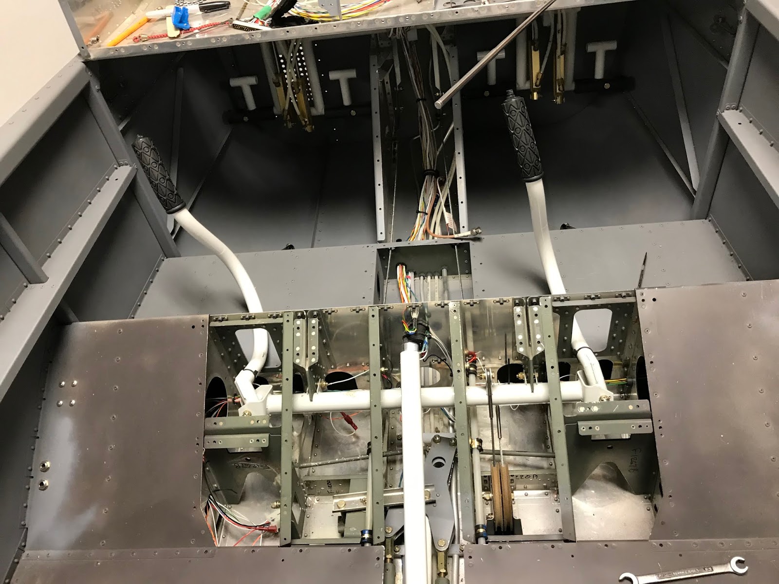
Over three riveting sessions I installed all the aforementioned pieces along with the fuel-sender plate (actually two circular plates), which doubles as an access panel should a need arise to get back into the tank after it's sealed, a horrifying prospect which came true twice.

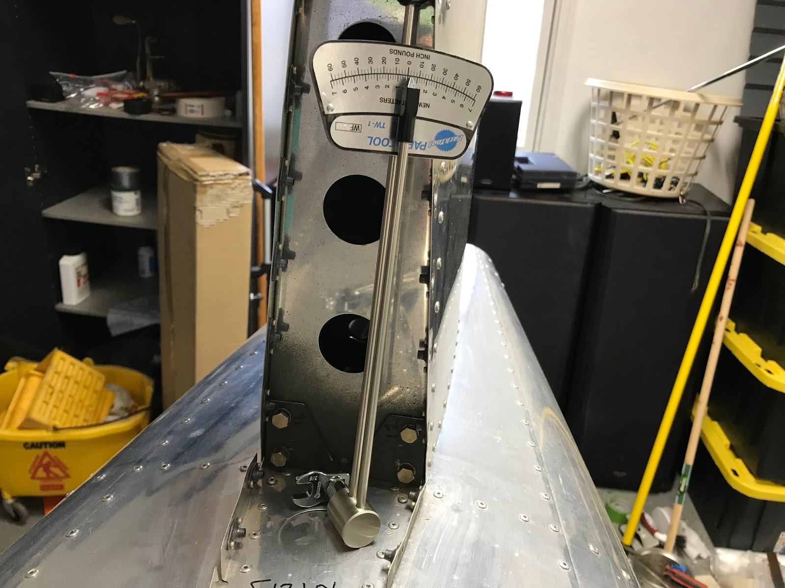
The assembly is to be leak tested after allowing the ProSeal to set up for several days by attaching a ballon to the tank, pressurizing the tank until the balloon inflates, then spraying soapy water all over the tank and looking for bubbles.  The balloon limits the pressure to something which won't cause the sealant to fail, supposedly less than one psi.  Being a curious sort, I decided to measure the pressure required to inflate a balloon by constructing a manometer. Turns out that every balloon I inflated needed about 1/3 psi (8 inches of water).  It took more to initially inflate it, but once stretched, 1/3 pis did it.  The Mothership says pressurize to one psi, but as long as I have a big enough delta P to blow bubbles, I think I'm good.  And blow bubbles I did.

With bated breath I pressurized the tank and proceeded to squirt the soapy water all over it.  Leaks appeared in six places.  After the misery of building the tank, it was as if someone had stepped on my soul. As Tom Cruise's sidekick said in Risky Business, sometimes you just have to say WTF?  I had
followed instructions, had done each procedure carefully, and this!  WTF!  At this point I had no choice but to open the tank, which involves inserting a putty knife between the access cover and the tank, removing the cover, then re-sealing all the offending sites from the inside.  The group wisdom of the Van's Air Force forums (and the Mothership) said don't be tempted to try it from the outside!

Turns out, contrary to what other blogs said, opening the tank was easy.  This should have been my first clue that the batch of ProSeal was bad, but it didn't occur to me yet.  I opened the tank, applied more ProSeal to the offending areas, and repeated the balloon test.  More leaks (picturing now a razor blade making lengthwise cuts of the arteries in my wrists).  I resigned myself to once again opening the tank and proceeded to do so.

This time it's almost impossible to do, far harder than the first time.  Bad sealant the first time!  I know I was within the shelf life, but it was bad.  I now bought a quart of ProSeal from the Mothership
and a digital scale from the aviation aisle at Harbor Freight, and did it all again.  Incredibly, there was another leak in the center of one of the rivets that was supposed to be "solid."  Rivet failure!  No way would I open the tank a third time.  I applied a suction to the tank, filled a cut-off syringe with ProSeal (needle removed, of course), and applied as much pressure as I could to the center of the rivet from the outside.  Success!

My rig for pressurizing the tank is shown at left: a 12-volt emergency pump for cars.


After letting the ProSeal cure for a couple of weeks, I put seven gallons (limiting the weight to about 50 pounds) of ethanol-free gas in the tank.  Over the course of a few days I turned the tank so that five of the six sides were down (didn't put it on its top), letting it sit this way for a day or so, and observed no leaks.  Of course, in the airplane the tank will be flexing somewhat, but I can't simulate that.

Boats don't have this problem.  The tank should be made of nylon or plastic or anything but riveted aluminum.  Horror stories about leaking tanks are plentiful on the forums, even the factory-made ones.  This now resides at the top of my Worst Jobs of the Build list, above the landing light and the tail cone fiberglass fairing.


Off Topic

This past summer I made my 31st pilgrimage to Mecca. Hard to believe I've been to Oshkosh that many times.  Can't wait for next year!  While there, I spoke with an insurance broker who told me that due to my age (hard to believe I'm 55....Oh, wait....) I should be insured and flying before another birthday happens.  Gotta be in the air before next September.  I'm on a waiting list for a hangar in Colorado and NC.

Monday, March 4, 2019

Painting the interior (while trying to build the gas tank)

For various reasons, I decided to go ahead and build the gas tank, something I expected to be an odious task and it didn't disappoint.  The building of the tank involves choreographing the rivet installations (eight different kinds I think), each of which must be cleaned with naphtha and smeared with the Devil's Own Glue called Proseal (it actually has a new name but everyone still calls it Proseal), which has a two-hour pot life.  Reading ahead in the build manual, I saw that one part of the tank build required centering the filler neck in a hole in the turtle deck.  Well, it turns out that I had
delayed installing the turtle deck to give plenty of room to do some critical drilling in the flaperon actuation linkage when that got installed.  I therefore needed to proceed with the installation of the flaperon linkage, the first instruction of which read "Install the wings."  In a post back in May (the subtitle of which is "dumb-assery on display") I detailed my attempts to persuade the wing spars to fully insert into the fuselage (didn't happen).  I now had no choice but to complete the wing installation.  The gas tank and the wing fit will be described in a future posts.

For some reason people who build RVs like to paint the interiors gray.  I'm no exception, although the dark gray I had envisioned couldn't be found in flat or matte finish.  Custom colors can be had in a rattle can but the cost is prohibitive.  I had primed the inside surfaces of all panels forward of the rear bulkhead using NAPA 7220 which is light
gray.  I finally settled for Krylon Colormax Matte Deep Gray as a top coat for everything but the roll structure (shown above).  The roll bar is still in primer, but it's hard to see the difference in the pic.  I definitely wanted a darker color for the roll structure, so once again I settled (like settling for a girl friend when you're sure you could do better but you're tired of looking) for Rust-oleum Universal Metallic Flat Soft Iron.  I found both of these on the aviation aisle at Lowe's.  In reference to the aforementioned settling, I put all that permanently behind me when, after looking for love in several wrong places, I committed holy matrimony with Dr. KTH (as her students call her) in 2009.

After painting everything but the roll structure, I masked as shown in the pic and painted the roll bar and the longitudinal member running aft from the roll bar which is not visible in this view.
All in all, I'm happy with the results.  Adding the turtle deck made everything look much better (last two pics).  We're on spring break, so I'm off the rest of the week and should be able to complete the tank.  I resisted the urge to spend the week in Colorado.  My webcams at my house there show a lot of snow, so I made a good decision.

Looking at my blog, I noticed that I haven't posted since attending the Oshkosh show for the 30th time last July.  The highlight of the show, I suppose, was watching the Van's crew and thousands of volunteers build the One Week Wonder, a complete, flyable RV-12iS built in one week.  Made me feel kinda bad considering I've been working on mine since 2011.

Saturday, June 16, 2018

(Page 12A-01) Stabilator tip fairings

The stabilator on the RV-12 as built to plans has squared-off tips, giving it, in the opinion of most builders it seems, an unfinished look.  I always sort of liked the look, but very much disliked the tooling holes (12 or so can be seen in the pic below) in the end ribs as well as the many holes in the wing tips where the tabs are bent and riveted and other holes in various places on the fuselage.  I'm convinced that all these holes were left
there in order to dirty up the aerodynamics to keep the speed below the LSA limit of 120 knots.  My plan all along has been to embark on an extensive aerodynamic clean up as soon as the FAA hands me the airworthiness certificate.  The stabilator also was limited to exactly an eight foot span to keep it legal for trailering on the highway.  Tips put it over the limit.

A couple of after-market companies make and sell rounded tip fairings and I've seen quite a few RV-12s with them installed (legal only after the airworthiness certificate has been awarded), but I couldn't decide if I liked them, other than the fact that they close all the offending holes.

Then, fairly recently, the Mothership got in the game and offered an officially-blessed kit.  What actually pushed me over the edge was doing the recent service bulletin 18-02-02 (covered in the previous post).  Complying with this SB involved drilling out a lot of rivets (punching their steel mandrils into the interior of the spar box) and drilling a lot of new holes in the spar box.  All this
resulted in quite a bit of debris in the spar box where it couldn't be reached.  It occurred to me that removing the end ribs as required to install the new tips might allow me to shake out a lot of the debris.  It still had to exit the few holes in the sides of the spar box, then make it through the lightening holes in all the ribs.  I could hear all the crap rattling around in there and I couldn't stand the thought of flying that way.  Tips it would be!

Installation of the tip kit involved drilling out 94 rivets to remove the existing end ribs (remember, I have achieved world-class status as a rivet remover), then replacing the end ribs with new ones reversed so that the flanges are out rather than in.  With the end ribs out, the shaking commenced in the driveway outside the shop.  I may have resembled a sign-spinner on a street corner in LA.  Along with a small amount of metal, I started seeing bits of shredded fabric, and I knew immediately
what that meant: mice had built a nest (shown in the pic above) in the spar box.  Visions of metal severely corroded by mouse urine danced through my head.  Inspection with a super-bright flashlight showed the nest to be not far from one of the few holes in the spar and I was able to hook most of it with a bent coat hanger and extract it (shown in the picture above).  A sudden epiphany lead me to tape a flexible piece of PEX tubing to the Shop Vac hose.  With this rig (pic at left) I was able to suck out not only the remaining bits of the mouse nest but all the metal debris which started all this.

At this point I inspected the entire interior of the stabilator with a bore scope to look for mouse urine corrosion.  Happily, the only spots I found were on the end ribs which were removed and replaced with the new ones in the kit.  A few small corrosion spots were found on the interior skin adjacent to the end ribs.  These were sanded and primed.

I keep live-capture traps set all the time in the shop (yeah, I'm that tender hearted), and had trapped and relocated a couple of mice a year or so ago.  Nothing since.  They had to be the culprits.

The new end ribs have to be straightened by fluting the flanges, just like all the other ribs in the
airplane.  The kit instructions say to modify the fiberglass flanges which slide underneath the rib flanges, making appropriate notches to clear parts of the spar, shop heads on rivets, and the humps produced by the fluting.  Lots of trial fitting here.

The instructions say to trim the fiberglass flanges to 15/32nd of an inch, which really means something less than 1/2 inch.  If this isn't done, the flange won't slide all the way in.  I used a Dremel tool with a sanding drum to "scallop" the fiberglass flange to
clear the fluting humps.  Files were used to make the rest of the notches.  I was not completely pleased with the cosmetics of the finished product, but I keep telling myself that perfection is the enemy of flying your airplane.