Friday, August 25, 2023

Page 38: Finishing the cowling (good riddance!)

Cowling Par Deux

At the end of the previous post I described how I'd managed to somehow over trim the fiberglass, in spite of countless trial fitting iterations, along the seam where the top and bottom cowls join.  For a while I thought I'd come up with a solution.  Before drilling the rivet holes for the piano hinges which hold the


two halves together, I used clear packing tape to hold the cowl halves in alignment while drilling the upper cowling and piano hinge.  The pin had been inserted into the two hinge halves, holding everything in place.

It seemed to work well, drilling and clecoing front to back


With the drilling done and all the countersinking done in the fiberglass, I squeezed all the solid rivets and proceeded to install, for the first time, both cowlings with all pins inserted.

Since everything was riveted in place now, with no room for adjustments, the two curved pins along the aft edge of the top cowl were, to put it mildly, a (suppressing the urge to swear) problem.  They had been difficult before but now seemed impossible.  Dry Boelube helped, but not enough.  I ended up inserting some spare pin material into the hinges, chucking it up in my drill, and spinning it a bit.  This opened up the holes in the hinges enough to allow insertion of the curved pins.  The gaps between cowl halves looked good as did the gap between the prop spinner and the front face of the cowl.


What a clever builder I am!  I got to enjoy this fantasy until doing the next step: Fiberglass in the cooling duct.

The cooling duct as supplied is of necessity too large, requiring another iterative session of fit-mark-trim-fit-repeat.

The duct takes in the ram air just behind the prop and directs some of it to the oil cooler, which attaches to the duct, and the rest to the coolant heat exchanger which doubles as a heater core for cabin heat.


The fit between the duct and the lower cowl doesn't have to be perfect since the duct is epoxied to the cowl along with fiberglass cloth, making it easy to fill any gap.

The hard part is getting the duct to interface correctly with the face of the coolant heat exchanger which is attached to the airframe. A deformable rubber seal helps a little.

When the duct is satisfactorily fiberglassed to the lower cowl, before the epoxy sets up, the upper and lower cowls are attached to the airplane with all piano hinge pins and screws inserted.  This is supposed to ensure that the final fit is good.  The problem is that the duct is a large, rigid piece which inevitably distorts the lower cowl a bit, screwing up the perfect fit which I bragged about earlier.  Now the seems are no longer perfect.  C'est la vie.


At this point I fabricated and riveted in the oil cooler door, using the RV-12iS plans which include a nice holder for the oil cap riveted to the inside of the door.

The NACA duct used to cool the voltage regulator was fitted and glassed in.  I'm siffck of fiberglass.


Off Topic: more Colorado wild life.

My home in North Carolina was waterfront on beautiful Badin Lake, a 5500 acre reservoir 25 miles east of Charlotte.  There were quite a few nesting pairs of Bald Eagles there, so seeing them fly by was common, but never got old.  I never had one land on my house, however, until I moved to Colorado.


Friday, January 20, 2023

Page 38 (Page 37 iS): Cowling

From the start, I realized that the instructions in the build manual for the cowling installation made no sense to me.  I was supposed to fit the cowling before installing the engine, fitting the bottom cowl first, independent to the top cowl.  Most of the group wisdom contained in the Van's Air Force forums advised to install the engine first, which I did, so the cowling could be installed relative to the engine.  To me, the most visible indication of a good-fitting cowl is the way the top cowl fits relative to the spinner.  Any lack of concentricity is immediately obvious.  At this point, I was still following the

build manual for the ULS engine (my engine) which has the builder trim the top and bottom cowlings to the factory-marked scribe lines (marks in the gel coat) and proceed from there.  I did this and it turned out to be OK since trimming beyond the scribe lines was required in all cases (otherwise I'd have been screwed).  

I first trial fitted both top and bottom with duct tape to get a general feel for what had to happen, then proceeded with the top cowl first.  I leveled the top cowl as described in the manual, using a long spirit level and plumb bobs hanging from the front corners of the top cowl.  Amazingly, the floor in my hangar turned out to be level, making this part easier.  I checked that both main tires were pumped to the same pressure and that the wing tips were the same distance off the floor.


At this point I decided to check the procedure for cowl installation for the newer 912iS (fuel injected) airplanes and discovered that this new procedure closely mirrors what I had just done: engine first, top cowl next, then bottom cowl.  I wish I had read this before starting work on this section!  It would have spared me the unease and frustration I was feeling for making such a large deviation from the manual, only to find that I was unknowingly following the new procedure.


After leveling the top cowl, the next task was to set the gap between the front face of the cowl and the rear bulkhead on the spinner.  I decided to set the gap at 1/8th inch, which allowed me to once again use the handy 1/8th inch spacers provided free by Lowe's in the form of paint stir sticks.  Thin double-sided tape worked great here.


If I had wanted a slightly larger gap (the manual recommends 3/16th inch) I'd have used stir sticks from Home Depot which are a bit thicker.


I love the way the small gap looks.  At Oshkosh 2022 I checked the gaps and general fit of the cowls on all the -12s in attendance (and other RV models, as well) and found mostly larger gaps.  Supposedly, larger gaps make for easier cowling removal, but I haven't found it to be a problem (yet).


The small piece of aluminum angle clecoed to the top of the cowl forces the vertical alignment of the cowling and the spinner, although a hangar neighbor who built an RV-7 says the cowling will sag a bit after a few hours of operation screwing up that perfect alignment.  

The Sharpie drawing just in front of the pilot seat is where I'll make the cutout for the NACA duct used to cool the voltage regulator.


Next, the aft edge of the top cowl is block sanded to match the forward edge of the aluminum skin covering the instrument bay.  All the #40 holes for rivets attaching the cowl to the soon-to-be-installed piano hinges are marked and drilled.  One errant #40 hole is shown.  I could've staunched the bleeding with a cleco in the finger tip, I suppose.


The cowling is held in place with duct tape throughout this procedure.  As with anything dealing with fiberglass on this airplane, it's an iterative process: trial fit (with tape), mark, remove, sand, trial fit, etc.  All of the marking is done with Vis-a-Vis Wet Erase.  The marks stay on well until rubbed with a wet finger tip (or paper towel if you grew up somewhere other than South Carolina).


The aft part of the piano hinge to which the finished cowl attaches was installed much earlier in the build (in my case probably seven or eight years ago).  The forward half of the piano hinge, to which the fiberglass is to be riveted, was fabricated (fluted to match the curvature) and installed with its pin.


At this point I fabricated all the piano hinges and pins.  There are two on top (one shown in the pic), two on each side which attach the aft edges of the bottom cowl to the airframe, and one on each side which attaches the top cowl to the bottom cowl.


With the aft half of each hinge installed, I proceeded to trial fit the bottom cowl.  Lots of on, mark, off, sand, fit, repeat.


It all went fairly well once I switched to the 912iS instructions. My only screw-up so far in this section was sanding off too much fiberglass from the interface between the upper and lower cowling (shown with the hinge clecoed at left) on one side.  I'm trying to decide how to recover from that and I'll describe it in part II of the cowling writeup.


Off topic

More Colorado wildlife: A few elk showed up behind my house recently.


A few large males cut through my front yard.

They better be glad I no longer hunt!


Monday, September 26, 2022

Page 47-03 Spinner


The spinner comes as a fiberglass cone with no cutouts for the prop blades and a bit too long.  The first task is to trim the length and cut out the slots for the blades.  A previously discussed bushing for the Pitot must be glued into the tip.  

After all the fiberglass cutting I've done for the project I've reached the conclusion that nothing beats a Dremel tool with a fiber cutting wheel.  With all the cutting for the cowling (coming soon to a browser near you) I bought Dremel's knockoff of a Fein tool (vibrating blade rather than rotating or translating), thinking it might put less dust in the air (and in my lungs -- I think facial hair prevents a good seal with the dust mask).  The Fein tool was overkill.  If there were a smaller, battery-operated version of this tool it might be perfect.


After that trimming, the spinner was trial fit as shown, being careful that the prop cutouts allow the inside of the spinner to press firmly against the forward and aft bulkheads. It was immediately obvious that the original cuts to the scribe lines were not enough.   Clamps held the spinner in this position for drilling.  As received, there are pilot holes in the front bulkhead for the nut plate center holes to be drilled in the spinner. 

At this point I checked the runout in the Pitot tube referenced to the sharpened nail pressed into the stationary board shown.  The point was centered immediately in front of the Pitot and the prop was rotated 360 degrees while checking for movement of the Pitot.  I did this with considerable trepidation, not knowing how I would fix it if the runout were unacceptable (>1/16th inch).  I could see no movement.

The center holes for the nut plates attached to the aft bulkhead were drilled using the drill guide that I cobbled together (shown below).  The lower plate rests against the aft edge of the bulk head flange, the middle plate is a spacer for the fiberglass, and the upper plate has the guide hole for the drill.  I made these out of scrap 4130 and held the sandwich together with vice grips.  This assured that all the holes were drilled in the correct axial location.  The aft edge of the spinner fiberglass extends a bit beyond the aft edge of the bulkhead flange and will be sanded flush once the nut plates are installed and the spinner is attached.


The holes for the solid rivets which secure the nut plates to the aft bulkhead required use of my TiteFit drill kit (shown below).  As I've said before, there are quite a few holes I couldn't have drilled without this thing.


The nut plates are held in place temporarily with a #8 screw while the #40 holes are drilled and attached with solid, counter-sunk rivets.


The final step is to construct the "gap fillers" which go behind the prop roots, ostensibly reducing drag.  These are made from the fiberglass pieces cut out in the first step.  I didn't realize this so I didn't make any attempt to make the cut with the Dremel tool as thin as possible.   This lack of reading ahead caused me to end up with a much wider gap than I'd like.  I'll probably fill it with micro later.


I hate setting solid flush rivets in fiberglass.  The countersink has to be made with the rivet head sitting a little proud of the fiberglass surface before setting.  Otherwise you'll crush the fiberglass a bit.  (Side note: When a part which should be flush with a surface instead protrudes a bit above the surface it is said to be a bit proud of the surface.  I'm trying to introduce a new term to the lexicon of aircraft fabrication: If a part which should be flush ends up a bit under the mating surface, it will henceforth be described as being a bit ashamed of the surface).  

There's definitely an art to getting solid rivets squeezed perfectly, even in metal.  With several of the solid rivets attaching the gap fillers to the flange I had the opportunity to exercise my considerable skill at drilling out solid rivets and re-doing them.  This hard-won skill is a testament to the number of times I've screwed up a rivet.


Off topic: Another one of my new Colorado neighbors.


Monday, August 22, 2022

page 47-07: setting propeller pitch


The propeller pitch is set by loosening the six bolts shown going through the front prop bulkhead into the hub, twisting the blades by hand, then re-torquing the bolts.  This obviously is an imprecise, trial-and-error process, made worse by the fact that the act of bringing the bolts up to the proper torque causes a very slight rotation of the blades.  The build manual says to set each blade to a specified angle within plus or minus 0.1 degrees (!?).  This is to be accomplished using a supplied steel bracket placed at a particular radial position on each blade and a digital level with a magnetic base.  The prop is leveled horizontally and the level is referenced to (zeroed on) the longeron.  Sensenich supplies different diameter metal "pegs" that are to be inserted into a hole in the hub to set the pitch to three different common angles but Van's says these can be off 0.7 degrees and therefore shouldn't be used.  


Here's the problem: The commonly available digital levels, most of which advertise accuracy of plus or minus 0.1 degrees, actually deliver this accuracy (if you read the fine print) only near 0, 90, 180 and 270 degrees.  Otherwise, it's 0.2 degrees, and I doubt it's actually that good.  

Since having each blade at the same angle is far more important than the actual angle itself (as long as you're close to the desired angle), I decided to use the laser built into my level to project a line on the floor (hard to see on the blue tape).  

My procedure went like this:  Use Van's procedure to get as close as the digital level will allow to the prescribed pitch angle for the first blade, mark the laser line on the floor, rotate the prop 180 degrees, transfer the bracket and laser to the second blade, twist the blade until the laser line is on top of the mark for the first blade.  Tighten. Tweak. The blades are at the same angle.


Off topic:  For the past nine months I've been having a house built in the hills west of Loveland.  There's lots of wildlife there so I've had a trail cam set up in the back yard (you can see the house in the distance).  During the cold months elk come down from the high country and hang around until spring.  Here's one pic.  My neighbor who lives about 1/4 mile away trumped it by showing me several video clips of two mountain lions at once in his yard.  Another neighbor had two moose in his yard and a bear rummaging through his trash can,  Ah, life in Colorado.


Friday, August 19, 2022

page 47-02: Pitot tube

The pitot tube on the RV-12 goes through the hollow propeller shaft and protrudes out the front of the spinner.  The tube itself is stationary while the prop and spinner turn around it.  This somewhat unusual arrangement was done to accommodate easy wing removal, making it unnecessary to disconnect the tubing for the Pitot each time the wings are removed.  


The thought behind the removable wings was that people could save money by storing the airplane at home and trailering it to the airport, avoiding the cost of a hangar.  I may have heard of one person who actually tried this while everyone else keeps the airplane at an airport in the usual fashion.

The Pitot tube as supplied has male threads on one end and is threaded into a rigid nylon block which is bolted to existing threaded holes in the gearbox housing.  If all the flat surfaces on the nylon block were at right angles to each other the forward end of the Pitot would be perfectly centered in the hole through the propeller hub.

As can be clearly seen in the second pic, it's way off.  I took everything apart and cleaned all the mating surfaces with no effect.  Somewhere a surface wasn't square with its neighbors.


After passing through this hole, the tube goes 
through a hole with bushing in the forward tip of the prop spinner.  Left like this, a constant radial load would be applied to the bushing, no doubt contributing to wear as some builders have documented on the forums.  I explained all this to the Mothership and was told it's fine.  Let the bushing handle it.


A few measurements and calculations showed that placing a 0.008 inch shim between the upper forward surface of the nylon block and the mating machined surface on the gearbox housing would bring everything into alignment.  The pic at left shows what that might look like if it were done.  If I were building Experimental-Amateur Build (E-AB) rather than Experimental Light Sport (E-LSA) I could do this sort of thing.  Since I am E-LSA I must build my airplane exactly like the ASTM Conforming Prototype, at least until I get my airworthiness certificate.  Then, oddly, I can do pretty much anything I want as long as I don't take it out of light sport parameters.


If I had used the shim, the Pitot tube would have been centered perfectly as shown in the pic at right, eliminating the radial load on the bushing.


Off topic:

I just got back from my 33rd trip to Mecca (a.k.a. Oshkosh).  After swearing last year I wouldn't do this drive again, I drove from Longmont, CO to KOSH and back, this year in a rental car (a little over 1000 miles each way).  Rental cars in Milwaukee were hard to get and expensive, not to mention the hassle and cost of airfare.  Turned out to be a good decision and I'll probably keep doing this even though my airplane will be ready for subsequent years.  I'm becoming increasingly nervous about parking my airplane outside in the elements for a week.  Maybe I'll change my mind.

In 2020 when I quit splitting my time between NC and CO and moved permanently to CO (selling my beautiful home in NC😢), I kept hearing local pilots talk about flying "over the hill" for breakfast or lunch.  Turns out they meant flying over the high mountains along the continental divide (Colorado has 53 peaks higher than 14,000 feet and 600 higher than 13,000 feet).  To a country boy from the Carolinas, this seemed like a serious undertaking.  I got my chance to try it a month or so ago when we attended an EAA fly-in breakfast in Granby, CO.  I got to go back seat in my hangar-neighbor Tom Book's RV-4 (got some stick time including pointers on formation flying).  This is a pic I took with my iPhone of my other hangar-neighbor Chad Rennicke's beautiful RV-6.  The building which contains my T-hangar has a total of 11 hangars.  In this building alone we have an RV-4, RV-6, RV-7, RV-10 under construction and my RV-12.


Tuesday, August 16, 2022

Pages 46-1 through 46-22. Engine prep and hanging

When the time came to actually hang the engine it was pretty exciting.  For the first time I would not need a stand under the tail tie down ring to keep the airplane from tipping over backward.  It could stand on its own three feet, proud and unsupported.  No crutch!  A quick perusal of the build manual, however, damped my excitement a bit.  A surprising amount of work was required to prepare the engine before hanging.


Since everything I was about to do required the use of a torque wrench, sometimes in awkward places where I couldn't see the dial on the Snap-On, I decided to calibrate the click-type Craftsman so I could use it if required.  In an earlier post I discussed calibrating the Snap-On with a known mass (not a bar bell weight!) and found it dead-nuts accurate.  A fresh calibration showed the same.  In the torque ranges required for engine installation the Craftsman was off by as much as 18%.  Glad I checked.


The first task requiring some thought was to check and set the five crank triggers shown in the picture below (five because one of them is a rev counter).  The gap between the tooth on the flywheel and the sensor is specified to be between 0.012 and 0.016 inches.  But wait a minute, I'm thinking, these Rotax

engines are broken in at the factory by being run on a dyno for about an hour.  Wouldn't that mean that the crank triggers are already set?  One  respected guy on the VAF forums just left them as is.  They're all tighter than the Van's spec, so I went ahead and set them.  This requires rotating the crank, which is accomplished by putting bolts in some threaded holes in the flywheel, removing a spark plug from each cylinder, and using a big screw driver as a lever.  When the prop is installed, turning the engine is much easier and has to be done a lot when fitting the spinner.  I still left the plugs out, however, with rags stuffed in the spark plug holes to keep trash and insects out.


The next challenging step required disconnecting four coolant hoses from the water pump in order to install the engine mount.  I've disconnected many a coolant hose on many a car over the years without any problem.  These were different.  Nothing I tried would budge them.  I finally fabricated the piece of wood shown and drove them off, still needing a little assist from the padded vise grips to supply a little rotation.  There was some coolant still in the engine which had to be caught in a shallow pan.


The engine mount is attached to the engine with four 10mm cap screws which must be accurately torqued to a hefty value which now escapes my mind but is obtained from Rotax Heavy Maintanence manual.  I was glad I checked the manual because it's a substantially higher value than is given in the standard bolt torque table.  The problem arises because it's hard to put a torque wrench on the upper


port-side bolt.  I've read where other builders removed the intake manifold to do this, something I really wanted to avoid.  These bolts must be rechecked at every annual condition inspection giving added incentive to find another way.  I ended up using a double box end wrench as a "torque adapter" as they're known commercially.  Keeping a 90-degree angle between the handle of the torque wrench and the box-end wrench means the torque reading in unaffected by the wrench (the position vector crossed with the force vector gives the torque).  There's a little segment of an Allen wrench in the end of the wrench not attached to the torque wrench which goes into the cap screw.


With the engine attached to the engine mount I was ready to move it to the airplane.  An engine hoist on rollers made this a simple, one-person operation.  Before attaching the mount to the firewall a couple of 3/8th inch holes had to be drilled through firewall, easy for me because I could do it from the front since I'd already installed the upgraded nose gear leg.  The poor souls who had to install the new leg to an already-flying airplane had to drill the holes from the inside, a much more involved task.


Wednesday, April 13, 2022

Service Bulletin 00053: I had my head in my tail cone!

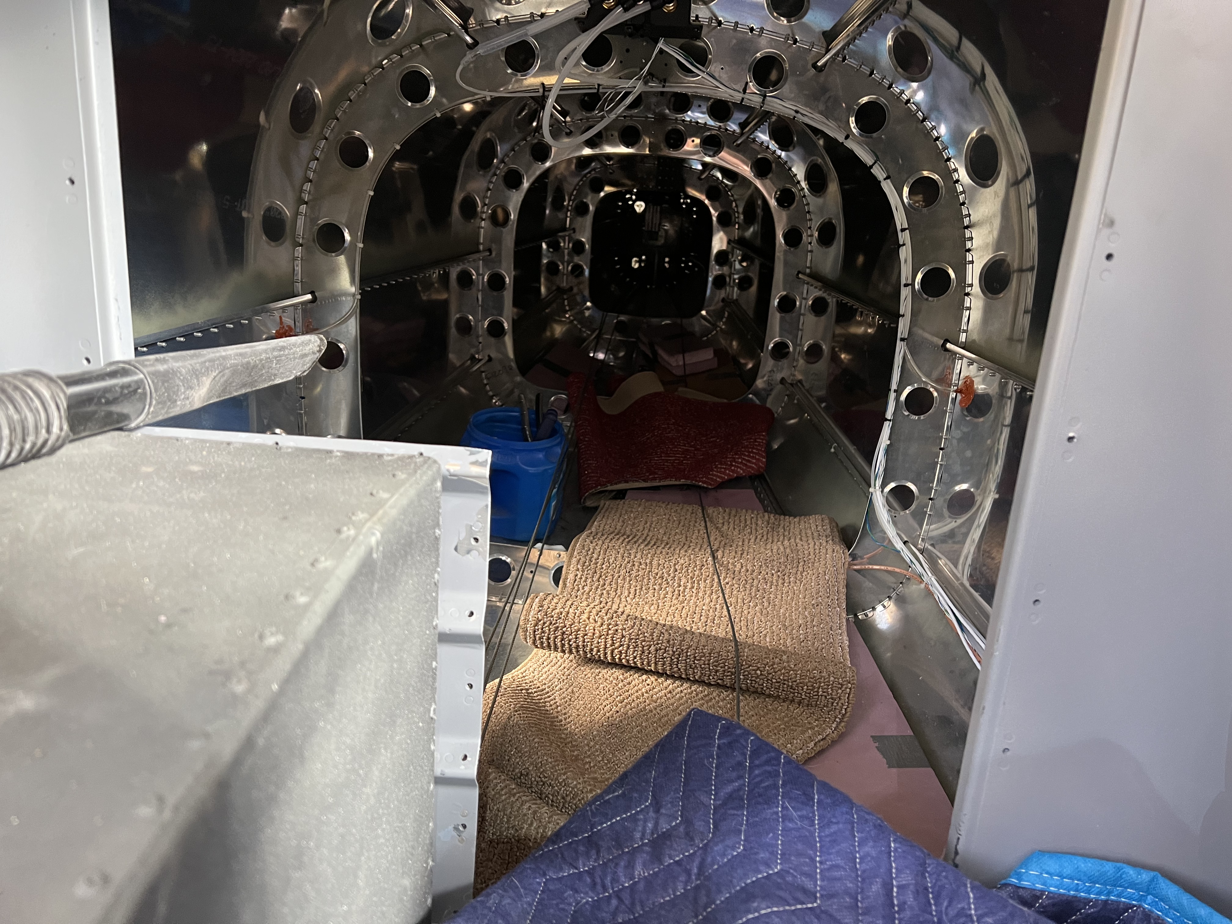
Recently, for several RV-12s, cracks in the skin of the tail cone have been discovered at the lowermost point where each of the three bulkheads attaches to the skin.  A structural member with a J-shaped cross section about an inch tall runs the length of the bottom of the tail cone but is discontinuous at the bulkheads, leaving the skin itself as the load path.  There are eight more of these stringers arrayed around the circumference and running the length of the tail cone, but each of them is a single piece of shaped aluminum (no discontinuity).  The Mothership ran an FEA analysis and decided that stiffening brackets needed to be riveted through the front and back of each bulkhead (except the aft most, which gets only the front) and to the skin, providing a load path and relieving the skin itself of some of its burden.  Sounds easy, and it would be if it were being done as the tail cone was originally built.  For an airplane with the tail cone already attached (with hundreds of rivets) to the forward portion of the fuselage, it's a massive problem, far and away the most onerous Service Bulletin to come out in the entire build.  A Service Bulletin for an airplane licensed in the Experimental category is roughly equivalent to an Airworthiness Directive for a store-bought airplane.  The picture shows the completed installation so you can get an idea what I'm describing.  If you click the pic and then expand it you can see the forward brackets installed at the bottom center of each bulkhead.  The aft brackets are hidden.


First off, the six rivets joining the skin to the stringers (remember, it's discontinuous) fore and aft of the bulkheads must be drilled out.  This is trivial since it can be done from outside the tail cone.  Then the three rivets joining the two halves of each bulkhead must be drilled out.  This, of course, must be done from inside the tail cone.  The five stiffening brackets are then clecoed in place (front and back except for the aft most bulkhead which gets only the front) and riveted.  This means a human being must somehow go inside the tail cone for its entire length and do all this.  The pic makes the inside of the tail cone look much bigger than it is.  Trust me.  Van's suggested, somewhat tongue-in-cheek I suppose, that enlisting the help of a smallish teenager might be appropriate.  The problem is that whoever goes back there has to have the skill to drill out the rivets without enlarging the holes and then set the new rivets.  I can't imagine trusting someone else to do this, especially someone who hasn't built an aluminum airplane before.


The instructions said to cut pieces of 5/16th plywood to place in each bay to support the load without damaging the skin.  I used pieces of 1-inch-thick foam insulation from the aviation aisle at Home Depot, doubled to give a stiff but soft place to put my knees and elbows.  I also used moving blankets and bits of carpet (which gave me carpet burns on my elbows, reminding me of my highschool years).  All this stuff and I were restricted to the left side of the tail cone because the tensioned elevator cables are on the right.

The third pic shows my work space (crawl space?) with all this stuff in place.  A bit of bad luck, completely by chance, manifested itself when I realized that when I built the tail cone I put the shop heads on the rivets forward rather than aft.  This meant that the rivets had to be drilled out from the aft side of the bulkheads.  When I made it to the aft-most bulkhead, I discovered that my head wouldn't fit past the stabilator counterweight, meaning I couldn't see to drill out the rivets, necessitating the use of a mirror, all while painfully perched on my elbows and

knees.  The gas tank on the lower left made it hard to get in and out, which had to happen several times per bulkhead.  If I had had an assistant to insert clecos from outside, the whole process would have been much easier.

I hear other builders saying this seems impossible.  The moral of this post is this:  If an old gimp like me can do this, any builder can.


Coming soon to a browser near you:  The Engine.